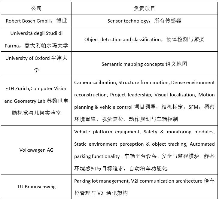
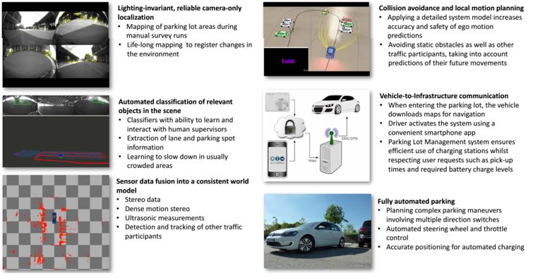
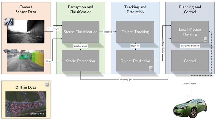
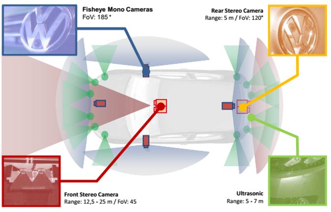
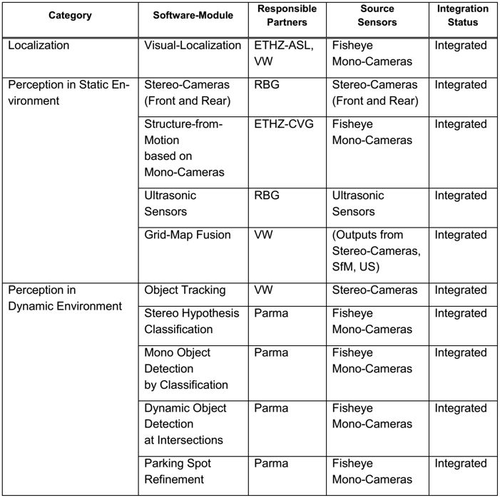
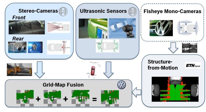
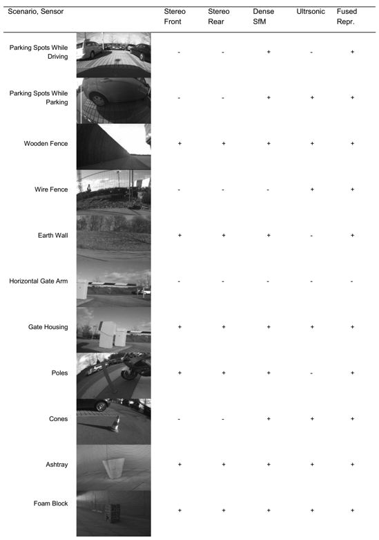
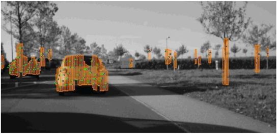
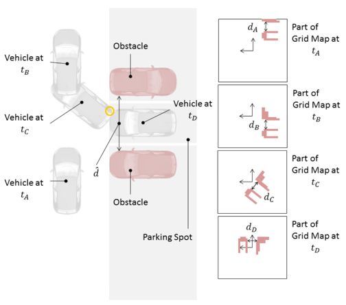
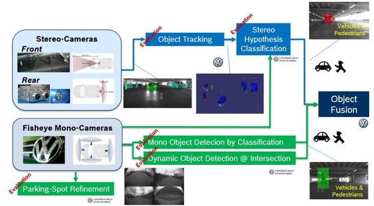
Valet Charge is abbreviated as V-Charge. Valet parking and charging is a research and development project sponsored by the European Union in 2011. The project started on June 1, 2011 and ended on September 30, 2015. The total cost was 8.695 million euros. The EU sponsored 5.63 million euros. After the end of the V-Charge project, Bosch, Volkswagen, and Mercedes-Benz are committed to industrializing it. The series of valet parking technologies we see from Audi, Mercedes-Benz and Bosch today are all derived from V-Charge. The project is led by the Swiss Institute of Technology Computer Vision and Geometry Laboratory, and is jointly completed by Bosch, Volkswagen, University of Oxford, University of Parma and Technical University of Braunschweig. German Carmeq and IAV companies also contributed. Valet Charge is designed for electric vehicles, mainly based on wireless charging parking spaces. Valet Charge envisages that the wireless charging system is buried under the parking space. The electric car is parked in the parking space and can be charged without any operation. This requires a high accuracy of the parking position, about ±10 cm. The idea of ​​wireless charging was very advanced in 2011, but the Valet Charge project did not consider the development of high-power wireless charging systems. Even today, wireless charging of electric vehicles is extremely rare. Back then, Volkswagen and the German robot company KUKA specially designed a charging robot. The robot will automatically remove the charging gun and insert it into the charging jack. Even today, this design is very advanced, and Volkswagen had this idea 10 years ago. Valet Charge contains six core technologies, which are still very advanced even today, ahead of some so-called fully automatic parking systems today. It is actually an L4 system for low-speed (less than 10 kilometers per hour) scenarios, and it also includes V2I technology and DTN network technology. We will introduce the core technology of Valet Charge in five parts. The first is perception, the second is map, the third is communication, the fourth is positioning, and the fifth is motion planning. The Valet Charge vehicle end frame is as above, the core is the same as the Mercedes-Benz, with binoculars as rod-shaped pixels, and grid possession method to provide navigation. The sensor layout of Valet Charge is as shown above, including two front and rear binocular cameras, 4 fisheye cameras, and 12 ultrasonic sensors. There is no rear binocular camera in the simplified version. All sensors are provided by Bosch. The front binocular camera has a baseline length of 12 cm and uses a 1.2 million pixel CMOS image sensor with a horizontal FOV of 45 degrees and a vertical FOV of 25 degrees. It can correspond to the low-light environment of the parking lot. Today, all Jaguar Land Rover series use this binocular camera. The effective distance is 12.5 meters to 25 meters, and the maximum distance is 50 meters, which is enough for parking lots. The rear binocular uses a 1.3 million pixel image sensor, the horizontal FOV is 120 degrees, the baseline is 5 cm long, and the effective distance is only 5 meters. The 4 fisheye cameras have 1.3 million pixels, a horizontal FOV of 185 degrees, and an effective distance of about 3 meters. The frame rate of all cameras is very low, only 8 frames, after all, the image processing ability in 2011 is not strong. There are 12 ultrasonic radars, of which 8 are front and rear short-range radars with a maximum distance of 1.5 meters, and 4 are long-range radars on both sides, with a maximum distance of 7 meters. The vertical FOV of the ultrasonic sensor is 60 degrees, and the horizontal is 120 degrees. The perception part is divided into three categories, namely positioning, dynamic environment perception and static environment perception. The positioning is jointly completed by the unmanned driving laboratory of the Swiss Institute of Technology Zurich and Volkswagen. For the static perception part, the front and rear binocular and ultrasonic perception are completed by Bosch, the monocular SFM is completed by the Computer Vision and Geometry Laboratory of the Zurich Institute of Technology, and the public completes the grid map integration. In terms of dynamic environment, the public completed binocular target tracking, stereo hypothetical clustering, monocular detection and clustering, dynamic target clustering, and parking space wireframe enhancement were all completed by the University of Parma in Italy with monocular fisheye. The above picture shows the composition of static scene perception, which can also be seen as the fusion of three sensors, including binocular, ultrasonic and fisheye cameras. The binocular is the core. Fisheye mainly uses SFM for 3D reconstruction, which is mainly used to make up for the shortcomings of the narrow binocular viewing angle. The binocular camera can provide the distance of hundreds of targets relative to the vehicle, but as long as the height of the target is within a certain interval, it is the height division. This method similar to the Mercedes-Benz rod-shaped pixels can directly obtain the free space (Free Space), or only provide the distance value of the obstacle. In order to make up for the lack of narrow binocular viewing angles and achieve 360-degree full coverage 3D scene reconstruction, fisheye 360-degree SfM is specially added. The full name of SfM is Structure from Motion, which is to determine the spatial and geometric relationship of the target through the movement of the camera, which is a common method of 3D reconstruction. The biggest difference between it and the Kinect 3D camera is that it only needs an ordinary RGB camera, so the cost is lower, and the environment is less restricted, and it can be used indoors and outdoors. The disadvantage is that it can only target low-speed, small-space occasions, and consumes computing resources very much. The SfM algorithm is an offline algorithm for 3D reconstruction based on various collected disordered pictures. Before proceeding to the core algorithm structure-from-motion, some preparatory work is required to select the appropriate picture. First extract the focal length information from the picture (required to initialize BA afterwards), then use feature extraction algorithms such as SIFT to extract image features, and use the kd-tree model to calculate the Euclidean distance between the feature points of the two images to match the feature points, thereby Find the image pair with matching number of feature points. For each image matching pair, calculate the epipolar geometry, estimate the F matrix, and optimize and improve the matching pair through the ransac algorithm. In this way, if there are feature points that can be chained in such a matching pair, and have been detected, then a trajectory can be formed. After entering the structure-from-motion part, the key first step is to select a good image pair to initialize the entire BA process. First, perform the first BA on the two pictures initially selected, and then add new pictures in a loop to perform a new BA. Finally, until there is no suitable picture that can be added, the BA ends. Obtain camera estimation parameters and scene geometric information, that is, a sparse 3D point cloud. The bundle adjust between the two pictures uses the sparse beam adjustment sba software package, which is a nonlinear least squares optimization objective function algorithm. Toshiba's fourth-generation visual recognition chip has added the SFM hard core. SFM is still good in a low-speed, small space like a parking lot. Of course, compared with binoculars, it still has a large accuracy gap, and its robustness is not strong. It also requires a wheel speed encoder. The accuracy of the front binocular and ultrasonic is very high, and the accuracy of SFM is very poor. The grid map is completed by the public, and the local action planning relies on the grid map. The map integrates multiple sensor data to clearly indicate obstacles. After the sensor data is updated, Bayesian filtering is used to determine the grid occupancy probability. Volkswagen uses two kinds of grid maps. The first is the driving layer, which is used from the entrance of the parking lot to the parking space after the driver leaves the car. The size of each cell is 0.1 meters, and the overall size is 50 meters. Completed by the front binocular. The second layer is the parking layer, the cell size is 0.05 meters, and the overall size is 25 meters. Front and rear binoculars, fisheye 3D reconstruction and ultrasonic data fusion. The picture above is a schematic diagram of a grid map of the parking layer The picture above shows the dynamic perception framework of Valet Charge, which is the fusion of binocular and fisheye camera. Dynamic environment perception is mainly target tracking and recognition of dynamic targets. Parking lots mainly have two kinds of dynamic targets, vehicles and pedestrians, which are relatively simple. Target tracking is actually used for dynamic target motion prediction. The optical flow method can accurately predict the target motion trajectory, but it is useless for the public. It just uses a simple extended Cayman filter, because the optical flow method consumes more computing resources. 2011-2014 is still relatively difficult to achieve, but the binocular optical flow method is relatively easy, but in Valet Charge, Volkswagen did not mention the binocular optical flow method, it may be because Mercedes-Benz holds a patent for the binocular optical flow method. In 2011-2014, binocular sensors and 360-degree panoramic cameras are quite rare. Now Mercedes-Benz, BMW, Jaguar Land Rover and Lexus LS series can be equipped with binoculars, and there are also 360-degree panoramic views, which provides the basic conditions for Valet Charge. 24V Battery Pack ,Large Battery Pack,24 V Battery Pack,24V Lithium Ion Battery Pack Zhejiang Casnovo Materials Co., Ltd. , https://www.casnovonewenergy.com
