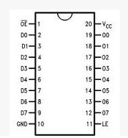
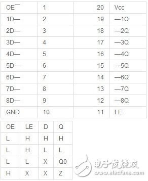
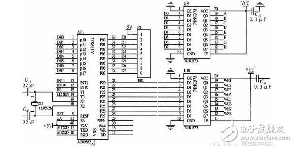
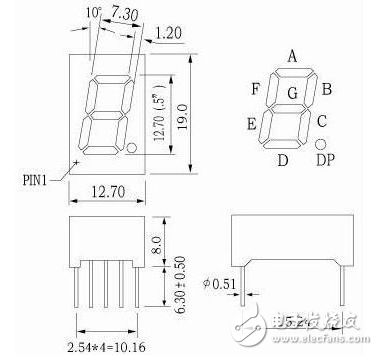
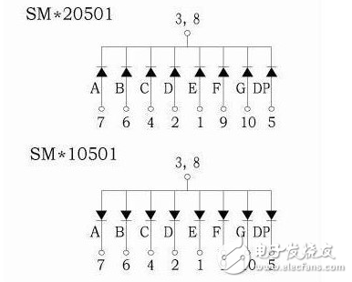
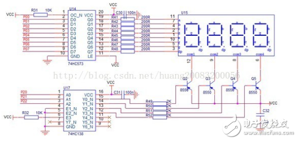
74HC573D is an 8-bit three-state latch, which is generally used for address or data latching in practical application circuits. This article mainly discusses the role of 74HC573D in the actual application circuit and how to drive the dynamic display of the digital tube. Here we will introduce 74HC573D one by one. Everyone knows that 74HC573D is a kind of latch, so why is the latch used? The so-called latch means that the state of the output terminal does not change with the state of the input terminal, and the input state is saved to the output only when there is a latch signal, and does not change until the next latch signal arrives. The typical latch logic circuit is a D flip-flop circuit. PS: Latch signal (that is, the input signal of the Data terminal when LE is set high). Latching means temporarily storing the signal to maintain a certain level state. The main function of the latch 1: Cache, 2: Complete the high-speed control of the asynchronous problem with the slow peripherals, 3: To solve the problem of driving (the current provided is larger than the output current of the 51IO port) I/O port multiplexing: When the single-chip microcomputer is connected to an off-chip memory, a latch must be connected to achieve address multiplexing. Assuming that the 8 I/O pins of the MCU port are to be used for both address signals and data signals, then the address can be latched by the latch. (Specific operation: first send the address information, the ALE enable latch will lock the address information into the address end of the peripheral, then send the data information and read and write enable signals, read and write at the specified address) If the bus interface of the single-chip microcomputer is used for only one purpose, no latch is required; if the bus interface of the single-chip microcomputer is used for two purposes, a latch is necessary. For example: an I/O port needs to control two LEDs. When sending data to the first LED, "open" the first latch and "lock" the second latch, so that the The data remains unchanged. When sending data to the second LED, "open" the second latch and "lock" the first latch so that the data on the first LED remains unchanged. If one port of the single-chip microcomputer is used for three purposes, three latches can be used, and the operation process is similar. In terms of this kind of usage, the latch can be regarded as the expander of the I/O port of the microcontroller. 74HC573 pin layout Data latch When the input data disappears, the data remains at the output of the chip; this concept is often used in parallel data expansion. From the truth table above, it can be seen that when OE is high, the output is always high impedance. At this time, the chip is in an uncontrollable state, so in general applications, we must connect OE to low level. LE is the output terminal status change enable terminal. When LE is low, the output Q always keeps the last stored signal (input from D terminal). When LE is high, Q follows the state change of D. And latch the state of D. That is to say, when the latch enable terminal LE is high, the latch of these devices is transparent to the data (that is, the output is synchronized). When the latch enable becomes low, the data that meets the setup time and hold time will be latched. In addition: the input to the latch is compatible with standard CMOS output; if the pull-up resistor is added, they can be compatible with LS/ALSTTL output. Detailed explanation of the circuit connection and use of the latch: (Combined with the latch pin description above) 0: Needless to say more about vcc gnd power supply? 1: OE ground 2: D0-D7 connect to our signal transmitter (usually the I/O port used by the microcontroller to transmit data) 3: Q0-Q7 connect to the terminal we want to receive information (digital tube, LCD, or any other device) 4: LE is connected to an I/O port (this I/O pin can be regarded as the switch of the latch latch function, the high level is to update the Q terminal signal (the signal to be updated is input from D), and the low level is not updated ) Take the pulse data acquisition circuit as an example. As shown in the figure above, AT89S52 and two 74HC573 latches are used to transmit information. AT89S52 has low power consumption, high performance, 8K bytes of Flash and 32-bit I/O ports. Line, full-duplex serial communication port and other advantages. Among them, the U10 latch is used for bit selection, and the U9 latch is used for segment selection. This can effectively expand the I/O port of the AT89S52 microcontroller P2, so that the program control information and pulse data information can be very effectively controlled during the transmission process , Which provides an important basis for the acquisition of multi-channel pulse data. Because the digital tube has strong luminous brightness and good indication effect, it is very suitable for numerical display applications such as elevator floors. For a digital tube, static display can be used, but in practical applications, it is necessary to display multiple values, and the digital tube module can only display dynamically. In the actual application circuit, the 74hc573 driving the digital tube is not simply a direct connection. This needs to be divided into specific application scenarios. The specific situation depends on whether it is simulation or physical. Simulation, 74HC573 can be directly connected to the digital tube. In kind, it is not possible. Each segment of the digital tube must be connected in series with a current limiting resistor. Here we only discuss the connection of 74hc573 in the dynamic display of the digital tube. Digital Tube The nixie tube is composed of a number of light-emitting diodes encapsulated together to form a "8"-shaped device. The leads have been connected internally, and only their individual strokes and common electrodes are drawn. The nixie tube is actually made up of seven luminous tubes in a figure of eight, and the decimal point is eight. These segments are represented by the letters a, b, c, d, e, f, g, dp. Digital tubes can be divided into common anode digital tubes and common cathode digital tubes according to the internal connection method. A common anode digital tube refers to a digital tube that connects the anodes of all light-emitting diodes together to form a common anode (COM) (SM*10501 in the figure below), a common cathode digital tube refers to a common cathode by connecting the cathodes of all light-emitting diodes together The digital tube of (COM) is as shown below (SM*20501). Take the common anode digital tube as an example, if you want to display the number 2, you need to light up the A, B, G, E, D segments, that is, connect the common terminal to the positive power supply, pull down the cathode of the ABGED segment, and pull the remaining segments high to display Number 2. Here takes the four-in-one common anode digital tube display as an example to explain its general design. No excessive current can flow through the IO port of the microcontroller. There is a current of about 10ms when the LED is lit. Therefore, the segment code output of the digital tube should not be directly connected to the IO port of the single-chip microcomputer. It should pass a buffer 74HC573. The IO port of the single-chip microcomputer only needs a small current to control the 74HC573 to indirectly control the display of the digital tube segment, and the 74HC573 output can also load about 10ms of current. Set the driving current of the nixie tube segment to ID=15ma. This current point has good brightness and a certain margin. Even if the output voltage of the power supply is high, it will not burn the LED. The current limiting resistance value R = (VCC- VCE– VOL– VLED) / ID VCC is 5v power supply, VCE is the saturation voltage between transistor C and E, estimated to be 0.2v, VOL is the voltage when 74hc573 outputs low level, different sink currents, this value is different, estimated to be 0.2v, see the specification for details, VLED is The red light driving voltage is estimated to be 1.7v. According to the above formula, the current limiting resistance can be calculated as R = 200R. The nixie tube needs to receive scan signals one by one. When the corresponding nixie tube is scanned, the corresponding segment data is valid, that is, the value of the nixie tube is displayed. I use a three-line eight-line decoder 74HC138 to generate the corresponding scan line signal. When each segment is lit, the current is about 15max8=90ma flowing through the common terminal of the digital tube. The 74HC138 cannot directly drive this current. It needs to be driven by a transistor. Since the 74HC138 output is low-level effective, only PNP transistors are suitable for driving here. The base current of the triode can be set to 2ma to saturate the triode, and the maximum drive current is much greater than 90ma. Base bias resistor resistance Rb=(VCC- VEB- VOL) ​​/ IB VCC is 5v power supply, VEB is the conduction voltage between transistor E and B 0.7v, VOL is 74hc138 output low voltage, which can be estimated as 0.3v according to the specification, so Rb= 2k. Schematic diagram of four-in-one digital tube The segment code of the nixie tube is connected to port P0, and the bit code is connected to digits 0~2 of port P2. There is a refresh rate for LED displays, and a scan rate is also required for dynamic scanning of digital codes. The lower limit of the scanning frequency is 50HZ, below a certain scanning frequency, the display will flash. If the frequency is too high, the brightness will be poor and CPU resources will be occupied. Generally, the scanning time of the entire nixie tube is about 10ms (that is, the scanning frequency is 100HZ). We use four nixie tubes. The lighting time of each nixie tube is 2ms, and the scanning time is 8ms. In order to ensure this refresh frequency, the digital tube is refreshed periodically through a timer. The author here uses the four-in-one digital tube to realize the stopwatch counting display as an example for code development. The content of the module file DigitalTubeTable.c is as follows: #include "reg52.h" #include"DigitalTube.h" // The segment code corresponding to the value, common anode static unsigned char codeDigitalTubeTable[12]= {// Common anode LED segment code table 0xc0, 0xf9, 0xa4, 0xb0, 0x99,0x92, 0x82, 0xf8, 0x80, 0x90, 0xff, 0xbf //"0" "1" "2" "3" "4" "5" "6" "7" "8" "9" "not bright" "-" }; // Each digital tube needs one byte of memory to save the corresponding digital tube data static unsigned charFrameBuffer[DigitalTubeNumber]; unsigned char*DigitalTube_GetBuffer() { return FrameBuffer; } void DigitalTube_Scan() { static unsigned char Select = 0; // Record scan selection line unsigned char Code; // Find the video memory data from the corresponding selection line and get the corresponding segment code Code = DigitalTubeTable[FrameBuffer[Select]]; // The segment code is actually output to the digital tube interface DigitalTube_Data(Code); // Bit selection is actually output to the digital tube interface DigitalTube_Select(Select); Select++; // Go to the next selection scan if (Select >= DigitalTubeNumber) { Select = 0; // All digital tubes have been scanned, start scanning again from the first digital tube } } We implement the interface access macro implementation of the module in the digital tube module header file DigitalTube.h to make it easy to transplant and modify the interface configuration. The module header file also leads to the module's interface function, void DigitalTube_Scan(void) is the digital tube refresh function, which needs to be called periodically to refresh the digital tube display. unsigned char *DigitalTube_GetBuffer(void) is used to get the display memory of the digital tube to update the display memory data of the digital tube. Its content is as follows: #ifndef __DigitalTube_H__ #define __DigitalTube_H__ #ifdef __cplusplus extern "C" { #endif // The number in the digital tube module, the maximum is 8 #define DigitalTubeNumber 4 // Output digital tube position selection #defineDigitalTube_Select(Select) {P2 = (P2&0xf8) + (Select);} // output digital tube segment code #define DigitalTube_Data(Dat) {P0 =(Dat);} // The refresh function of the digital tube must be guaranteed to be called in a certain period void DigitalTube_Scan(void); // Obtain the display memory of the digital tube to update the displayed data unsigned char*DigitalTube_GetBuffer(void); #ifdef __cplusplus } #endif #endif /*__DigitalTube_H__*/ The external module uses the module header file DigitalTube.h of the digital tube to realize the call of the digital tube driver function. The simple test call (stopwatch digital tube display count) is realized as follows: #include"reg52.h" #include"DigitalTube.h" // Take the timer time as the timing standard, record the time interval static volatile unsignedint SystemTick = 0; // Timer 2ms interrupt processing to refresh the digital tube void T0_Interrupt()interrupt 1 { TH0 = (65536-2000) / 256; TL0 = (65536-2000)% 256; SystemTick++; // Record time interval DigitalTube_Scan(); //Refresh the digital tube } void T0_Init() { TMOD = 0x01; // Timer 0 working mode 1 // 2ms timer interrupt (12M) TH0 = (65536-2000) / 256; TL0 = (65536-2000)% 256; ET0 = 1; // Timer T0 interrupt enable EA = 1; // Total interrupt allowed } void main() { unsigned char *pBuffer; unsigned char i; // Timer initialization T0_Init(); // Obtain the display memory of the digital tube to update the data display pBuffer = DigitalTube_GetBuffer(); // Data tube display memory initialization display 0 for (i=0; i pBuffer[i] = 0; } // Turn on the timer for timing and digital tube refresh TR0 = 1; while(1) { // When SystemTick reads 500, it is 1s interval to if (SystemTick> 500) { SystemTick =0; // Re-count the seconds // Update the display memory of the digital tube stopwatch count for (i=0; i pBuffer[DigitalTubeNumber-1-i]++; if (pBuffer[DigitalTubeNumber-1-i] break; // If it does not reach 10, update the high-order video memory without carry, and exit } else { For the 74hc573 latch, in the actual application circuit, if the bus interface of the microcontroller is used for only one purpose, there is no need to connect the latch; if the bus interface of the microcontroller is used for two purposes, two locks are needed. Memory. This is the end of the introduction to 74hc573, I hope this article can be helpful to you. Light Tower,Industrial Light Tower,Portable Lighting Tower,Electric Lighting Tower Wuxi Doton Power , http://www.dotonpower.com