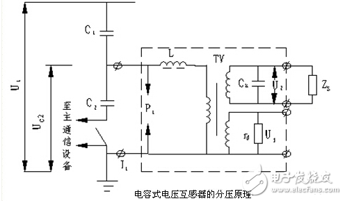
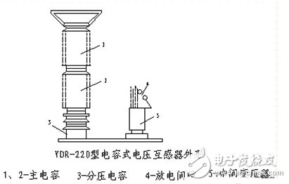
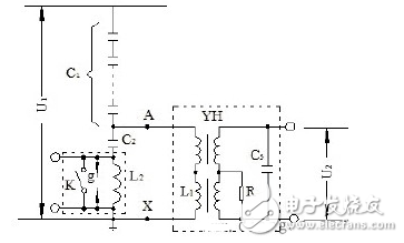
The capacitive voltage transformer is essentially a capacitive voltage divider. For the sake of analysis, the capacitor string is divided into two parts, a main capacitor C1 and a voltage dividing capacitor C2, as shown in the upper left figure. Let the voltage on the primary side be U1, then on C2 The voltage is: UC2=C1/(C1+C2)U1=KU1 In the formula, K=C1/(C1+C2) is a partial pressure ratio, and the ratio of C1 to C2 is changed to obtain different partial pressure ratios. Since UC2 is proportional to the primary voltage U1, U1 can be obtained by measuring UC2, which is the working principle of the capacitive voltage transformer. The capacitive voltage transformer is stepped down by the intermediate transformer and then connected to the meter. As shown in the left figure below, the main reason is that the output of the capacitor divider cannot be directly connected to the meter. Otherwise, the secondary load impedance will affect its accuracy. The function of the protection gap is that when an abnormal overvoltage occurs on the voltage dividing capacitor, the gap first breaks down to protect the compensating reactor, the voltage dividing capacitor and the intermediate transformer from being damaged by overvoltage. Compared with electromagnetic voltage transformers, capacitive voltage transformers have the advantages of high impact insulation strength, simple manufacturing, light weight, small size, low cost, reliable operation, convenient maintenance and high-frequency carrier communication coupling capacitors. . The main disadvantage is that the error characteristics are worse than the electromagnetic voltage transformer, and the output capacity is small, and there are many factors affecting the error (such as temperature, frequency, etc.). At present, the accuracy of YDR-type capacitive voltage transformers manufactured in China has been increased to 0.5, and has been widely used in direct grounding systems with neutral points of 110KV and above. Capacitor voltage transformer wiring diagram: In a system where the neutral point is not grounded or the arc suppression coil is grounded, in order to measure the relative ground voltage, the PT primary winding must be connected in a star grounding manner. In the 3~60KV power grid, three single-phase three-winding voltage transformers or one three-phase five-column voltage transformer are usually used. It must be pointed out that this measurement cannot be made with a three-phase three-column voltage transformer. When a single-phase short-circuit occurs in the system, a zero-sequence current will pass through the three phases of the transformer, producing zero-sequence flux of equal magnitude and phase. In the three-phase three-column transformer, the zero-sequence flux can only form a closed magnetic circuit through the air gap with large reluctance and the iron casing, and the zero-sequence current is large, which causes the transformer winding to overheat or even damage the equipment. In the three-phase five-column voltage transformer, the zero-sequence magnetic flux can form a loop through the iron cores on both sides, and the magnetic resistance is small, so the zero-sequence current value is not large, and no damage is caused to the transformer. Here you can find the related products in RandM Vape, we are professional manufacturer of RandM Vape. We focused on international export product development, production and sales. We have improved quality control processes of RandM Vape to ensure each export qualified product.
Whatever you are a group or individual, we will do our best to provide you with accurate and comprehensive message about RandM Vape!
RandM Vape,RandM Disposable Vape,RandM Vape Kit,RandM Vape Pod,Disposable RandM Ecig TSVAPE Wholesale/OEM/ODM , https://www.tsecigarette.com


If you want to know more about the products in RandM Vape, please click the product details to view parameters, models, pictures, prices and other information about RandM Vape.

Capacitor voltage transformer wiring principle
1. Working principle of capacitive voltage transformer