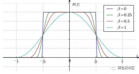
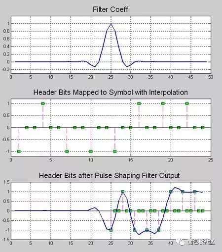
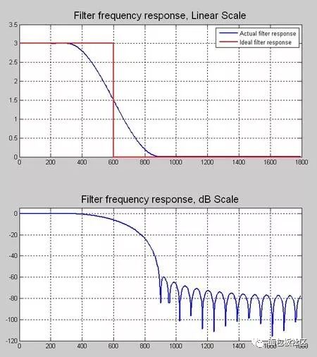
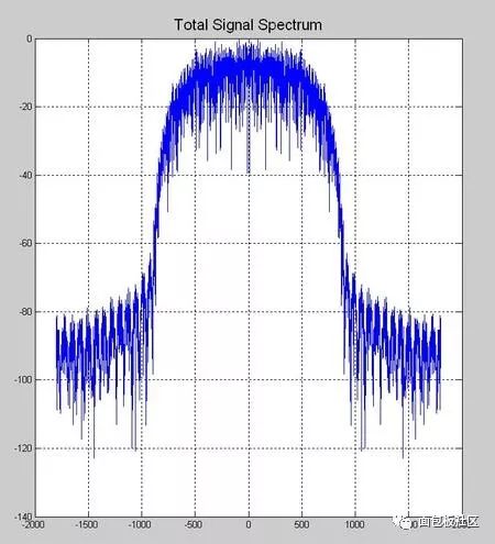
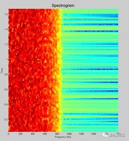
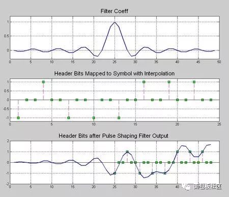
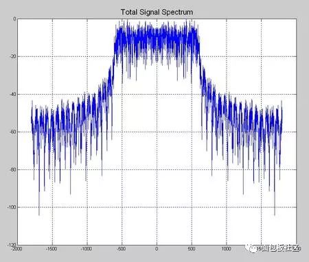
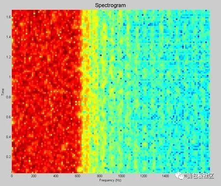
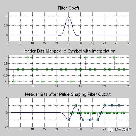
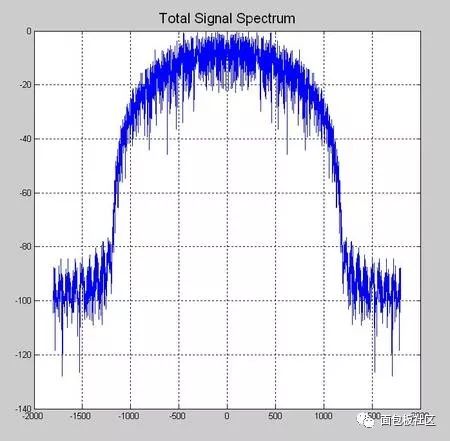
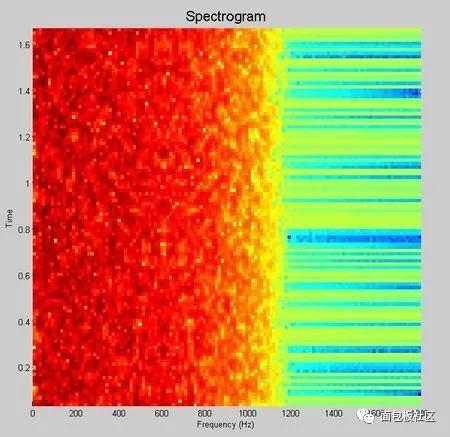
This time we explore another thing that gives us headaches in the undergraduate stage, the necessary course of communication principle, the content that must be backed up, and the baseband pulse shaping. However, the understanding and understanding of this thing is after the undergraduate course. In the early years (such as the Motorola mobile phone era), the baseband forming was done with analog circuits. At that time, the digital circuit density was extremely low. Think about the various 74 series chips in the undergraduate digital experiment. If you use this thing to spell a number. The filter is estimated to be mad. Moreover, even with digital filters, high-speed and high-precision ADCs and DACs are also a problem. Therefore, the name of the digital circuit textbook in the early years is usually called "pulse and digital circuit". The implication is that this thing is used to process the pulse signal, and it also processes the pulse signal. Don't think about it. Complex things, it will still be an era when analog circuits dominate the communication system. The problem is that in addition to calling, people still have the need to transmit data, such as wireless digital communication systems like pagers, even earlier, such as Zheng Junli's "Remembrance and Signaling and System Commentary". Mentioned his young artifact "1200 baud number transmission", this thing is called "1200 baud rate modem" in the present words, you will be sent to the Internet, you must be too slow, but at the time it was a national project A major issue. If you are willing to go to some communication principles or archetypes in the textbooks of the signal and system, you may see some exercises specifically discussing how to design a simulated raised cosine roll-off filter. In that era, the task of the digital circuit was to transform the bit information to be transmitted into a pulse signal, which is a series of square waves of various amplitudes (multi-ary modulation). We know in the course of signals and systems, square wave signals. The bandwidth is infinite, so the analog shaping filter of the latter stage is responsible for reducing the spectral bandwidth of these square waves, while at the same time satisfying the criterion of no distortion in the time domain sampling points. We have studied the IIR filter in the digital signal processing course, and there are also "bilinear transformation method", "impact response invariant method", and various things that make us dizzy. When I was young, I first learned this thing. I thought, what did this thing do, and later realized that this thing is to implement the previous analog filter by digital method. The analog filter has a pole, which is mapped to the digital domain, which is the IIR filter. So why replace the analog filter for two reasons. First, in order to improve the consistency of the communication products, the values ​​of analog components such as capacitors and resistors cannot be strictly and accurately produced. As for the inductance, it is a more unreliable thing. This causes each analog circuit component to be manufactured completely differently. If the analog component is used in a large amount in the system, the accumulation of the error will be a big problem, so the designer will add some parameter-adjustable components to the circuit in advance. In the final assembly stage, the worker master is watching the test instrument to manually adjust the product. The digital circuit is different. Once it is produced, the behavior is completely consistent. The later assembly and debugging links are greatly simplified, so it is more productive. If you have played the red alarm, StarCraft should know that rapid production is a big deal. The advantage of the above behavioral consistency is only one aspect. On the other hand, it is more attractive that there is a concept in digital circuits called "equal reduction". For example, the earliest computer has a house size, which may be handled in your mobile phone. I don’t have one percent of the computing power. I used to do some algorithms to go to the IEEE trans archaeology in the 1970s. I found that some scientists showed off the wealth in the chapters where the experimental data was posted at the end of the article. The running time on the IBM luxury mainframe with XX model with 1 Mbyte of memory was 12 seconds," I was embarrassed at the time. Therefore, you can't see the big guys in the current Hong Kong production police film. They have to be equipped with a younger brother to take the phone for him and to use the mobile phone to swear. If it is not to replace the filter of the analog era, or to adapt to the needs of some special adaptive filters, I will try to avoid the use of IIR filters, especially in the case of FPGAs. why? Because this pole filter is really sensitive to quantization noise, it is self-oscillation, and after being tweaked, it is tossed by the seven-six-seven-six, and then I will never use it again, or use FIR filter. Let the leader buy a big chip first. If it's on the processor, especially the CPU that supports floating point, it's fine to do it, but also pay attention to the filter. If the order is high, the IIR is still a dangerous product. Therefore, in the field of digital signal processing, the baseband shaping filter is usually selected as FIR. One of the things that requires extra attention when performing digital band forming is multi-rate, which is confusing. The device has two rates, one is the rate of the input symbol, and the input of the filter is a series of positive or negative pulse trains, which are obtained by symbol mapping of information bits to be transmitted, if multi-level Modulation, the burst will have a variety of amplitudes, the simplest mapping method is: information bit 0 is mapped to pulse symbol -1, information bit 1 is mapped to pulse symbol +1, what is this pulse symbol, that is, "Nyquibe The "sampling point is not distorted" sampling point mentioned in the "Standard criterion", this sampling point refers to the pulse symbol. Another rate, the sampling rate of the filter output waveform, cannot be less than 2 times the signal bandwidth according to the sampling theorem. Sometimes, for other reasons, such as simplifying the filter design, a higher sampling rate may be used. . Ok, here we have to show a seesaw, just like the time domain in the short-time Fourier transform, the frequency domain resolution is the two ends of the seesaw. This baseband forming design also has a seesaw, let us take a look. The so-called seesaw, that is to say, there are several parameters, and there are constraints between each other, adjusting one parameter, the other parameters will change accordingly, usually our approach is to fix a part first, then adjust another, then observe the adjustment result. Fortunately, there are only three parameters. According to the communication principle textbook, when using the raised cosine roll-off filter for shaping, these three parameters are: the rate of the pulse symbol Rs, the roll-off factor beta, the bandwidth of the generated narrow-band signal. BW, textbook said, BW = Rs (1 + beta) / 2, beta is a decimal between 0, 1, this expression is very simple, it illustrates the fact that for the symbol rate is Rs The pulse train, if the sampling point is to be free of distortion, and is transmitted with a band-limited signal, the bandwidth of the band-limited signal will be between 0.5Rs and Rs. At this time, one of our seesaws is the signal bandwidth, and the other is the frequency response shape of the filter. You can see the following figure, copied from the wiki, this beta=0 is the ideal low-pass for the "brick wall" card. This is not a joke, so if you want to transmit a fixed-rate pulse symbol, you need to make a high-performance filter that can approach the "brick wall" if you want to save bandwidth. Otherwise, it will take up more bandwidth. The fixed symbol rate is the fulcrum of the seesaw. In addition, we can also cite another case, for example, to fix the transmission bandwidth. At this time, the two ends of the seesaw are the filter roll-off coefficient and the symbol rate, which are essentially the same as the previous case, without losing the general Sex, let's discuss the symbol rate as a fulcrum. Here, we provide a piece of code that expresses a time-frequency characteristic of a signal generated by a 1200 baud/sec burst after passing through a differently configured shaping filter. The matlab function used by the shaping filter is rcosine. In addition to configuring the symbol rate, roll-off factor, and sampling rate of the output waveform, you also need to configure a filter delay. Is this parameter dry? The textbook of communication principle is not mentioned. The answer is in the textbook of digital signal processing. Because we know that the FIR filter is conceptually a multi-tap shift register, the problem is that once you specify the frequency response curve of the filter by the roll-off factor. The shape, in addition, is determined by how many tap FIRs you are going to implement to implement this filter. The more taps you have, the better the RF band rejection is achieved, but at the cost of computation and latency. OK, yes, you find that there is a seesaw. Note that the unit of the delay parameter for this function is the number of pulse symbols, ie the delay relative to the input. Let's start playing with this code. First find a moderate configuration, the roll-off factor is 0.5, the sampling rate is 3 times the symbol rate, and the filter delay is 8 (pulse symbols). Since the FIR is center-symmetric, you can see that the total tap coefficient is 3*8*2+1=49, you can see the time domain waveform of the filter impulse response through the map of the time domain below, and the input information bits are mapped to bursts with amplitudes of +1 and -1, and The zero-padding interpolation is done as the input to the filter. Then, in the filter output signal, you see if there is no distortion at the sampling point (please pay attention to those samples whose amplitude is +1, -1)? The original information bits of the signal in this time domain are 0x47, the famous frame header in the digital satellite standard. Hey, wait, do you feel a bit familiar, right? In fact, the digital shaping filter is an interpolation filter in multi-rate signal processing, which we discussed in the previous series. Roll-off factor of 0.5 Illustration, time domain waveform Then we look at the amplitude-frequency curve of the frequency domain, which is the linear scale and the dB scale. We see that the design cutoff frequency of this filter is 900 Hz, which is in accordance with the calculation of the formula, and the stopband attenuation of the implemented filter is - About 60dB. Illustration, filter frequency response Next, look at the windowed DFT spectrum of all the signals. Similarly, you can see that the attenuation is -60dB at 900Hz. Illustration, windowed DFT spectrum Then we look at the short-term amplitude-frequency characteristics of the STDFT (short-time Fourier transform) spectrum. Illustration, waterfall map spectrum Ok, the other parameters are unchanged, we change the roll-off factor, first the illustration with the roll-off factor of 0, the time domain waveform Brick wall is impossible to achieve perfection, unlimited approach, you look at this spectrum, remember the signal and system textbook, there is a word called "Gibbs phenomenon"? Pay attention to the filter's passband width and stopband attenuation, which is terrible -20dB. Illustration, filter frequency response This signal bandwidth is 600 Hz and the out-of-band spurs are large. Illustration, windowed DFT spectrum The same is true for short-term analysis. Illustration, waterfall map spectrum Next, change the roll-off factor to 1. Illustration, time domain waveform Illustration, filter frequency response Illustration, windowed DFT spectrum Illustration, waterfall map spectrum The communication system is indeed a complex and fragmentary discipline. I hope this article can do its best for your study. There have been poems on the Internet: If the sky is old, the communication is dead early. Business women do not know that the country is hateful, and the river is still watching information theory. Ask how many can you have, and the bit error rate will not be asked. The screams on both sides of the strait could not hold back and discuss the spectral density with each other. As the spring breeze comes, the signal flow diagram will not be arranged. If Luoyang’s relatives and friends ask each other, they will go directly to Han Shengdong. The wind is bleak, the water is cold, and the modulation and demodulation is difficult. Sit in dying, and test the noise ratio tomorrow! Here is the code snippet: %////////////////////////////////////////////////////// //////////% base band shaping use raised cosine FIR filter%//////////////////////////////////// //////////////////////////////////close all;clear;clc; Rate_symbol = 1200 ; % input symbol raten_itp = 3 ; % num of interpolationfilter_delay = 8 ; roll_off = 1.0 ; Head_bit = [0 1 0 0 0 1 1 1 ].';total_bit_len = 2048; bit_map = [-1 1] ; Head_bit_len = length(head_bit);info_bit = randint(total_bit_len-head_bit_len,1); Total_bit = [head_bit; info_bit]; Head_itp_len = head_bit_len * n_itp; Fs_filter_out = n_itp*rate_symbol % filter output sample rate Filter_delay_in_sample = n_itp*filter_delay ; Coeff = rcosine(rate_symbol, fs_filter_out, ... 'fir/normal', roll_off, filter_delay); Coeff = coeff .' ; % map info_bit to multi-level signalsignal_1x = bit_map(total_bit + 1) ; Len_1x = length(signal_1x) ; Len_itp = len_1x * n_itp ;signal_itp = zeros(len_itp,1) ;% write the original signal value into itp signalsignal_itp(1:n_itp:len_itp-n_itp+1) = signal_1x; Data_conv = conv(coeff, signal_itp); data_conv = filter(coeff,1, signal_itp);filter_out = data_conv ; Signal_itp_x_axis = [1:head_itp_len] + filter_delay*n_itp; Figure;head_itp = signal_itp(1:head_itp_len);head_conv = data_conv(1:head_itp_len+filter_delay_in_sample); Subplot(3,1,1); plot(coeff, 'linewidth',1.5); grid on; ylim([-0.3, 1.2]);title('Filter Coeff', 'FontSize', 16); Subplot(3,1,2); stem(head_itp,...'--ms', 'MarkerEdgeColor','k','MarkerFaceColor','g', 'MarkerSize',6);title('Header Bits Mapped to Symbol with Interpolation', 'FontSize', 16);ylim([-1.2, 1.2]);grid on; Subplot(3,1,3); stem(signal_itp_x_axis, signal_itp(1:head_itp_len), ...'--ms', 'MarkerEdgeColor', 'k', 'MarkerFaceColor', 'g', 'MarkerSize', 6 ;grid on; hold;subplot(3,1,3); plot(head_conv, 'linewidth',1.5);grid on;title('Header Bits after Pulse Shaping Filter Output ', 'FontSize', 16); Kaiser_beta = 8 ; Kaiser_win_spectrum_plot(fs_filter_out, filter_out, kaiser_beta);title('Total Signal Spectrum', 'FontSize', 16); Len_w = floor(total_bit_len /8); len_o = floor(len_w * 0.8); len_d = len_w ;figure ;% use tic toc get running timespectrogram(filter_out, len_w, len_o, len_d, fs_filter_out);title('Spectrogram', ' FontSize', 16);% get filter frequency reponse vector over 0~pi[f_rp_vec ,w_pi] = freqz(coeff);x_half_fs = w_pi/pi(fs_filter_out/2);f_rp_vec_norm_dB = 20log10(abs(f_rp_vec)+1E-10 );f_rp_vec_norm_dB = f_rp_vec_norm_dB - max(f_rp_vec_norm_dB); Figure;ideal_f_rp_vec = (x_half_fs < fs_filter_out/(2n_itp))n_itp; Subplot(2,1,1);h1 = plot(x_half_fs, abs(f_rp_vec), ...x_half_fs, ideal_f_rp_vec, '-r', 'linewidth', 1.5);grid on; Title('Filter frequency response, Linear Scale', 'FontSize', 16); legend('Actual filter response', 'Ideal filter response');subplot(2,1,2);plot(x_half_fs, f_rp_vec_norm_dB, 'linewidth ', 1.5);grid on;title('Filter frequency response, dB Scale', 'FontSize', 16);ylim([-120, 5]);
The composite terminal is a typical representative of the connector (CONNECTOR), which is composed of a plug (female) and a socket (male) to realize the connection function. For the transfer of voltage, current and signal, this series is characterized by safe, reliable and stable contact, and is mainly used in electric power, communication, industrial control and other industries.
composite terminal block,component terminal block,composite terminal block adapter Sichuan Xinlian electronic science and technology Company , https://www.sztmlchs.com