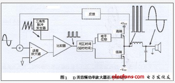
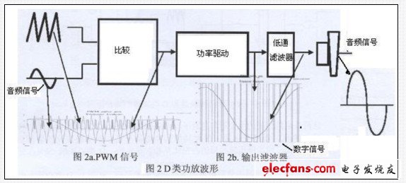
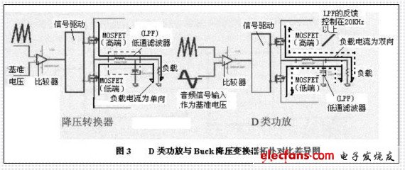
D power amplifier is a switching amplifier based on pulse width modulation technology, including pulse width modulator (a few hundred kilohertz switching frequency), power bridge circuit, low-pass filter. This article analyzes the basic issues related to the design of class D audio power amplifiers such as composition, topology comparison, MOSFET selection and power loss, distortion and noise generation, audio performance, and examples of class D power amplifier reference designs. 1. Basic composition of Class D amplifier There are many different types of power amplifiers, such as: Class A, Class B, Class AB, etc. But the difference between Class D amplifier is basically a switching amplifier or pulse width modulation amplifier. To this end, mainly to explain this class D amplifier. In this class D power amplifier, the device is either fully turned on or turned off completely, which greatly reduces the power consumption of the output device, and the efficiency of 90-95% is possible. The audio signal is used to modulate the PWM carrier signal. The carrier signal can drive the output device, and the final low-pass filter is used to remove the high-frequency PWM carrier frequency. As we all know, Class A, Class B and Class AB amplifiers are linear amplifiers, so what is the difference between Class D amplifiers and them? We should first discuss. Figure 1 is a block diagram of the principle of the D power amplifier. In a linear power amplifier, the signal always stays in the analog area, and the output transistor (device) acts as a linear regulator to adjust the output voltage. In this way, there is a voltage drop across the output device, which results in reduced efficiency. Class D amplifiers take many different forms, some are digital inputs, and some are analog inputs. Here we will focus on analog inputs. Figure 1 above shows the basic functional diagram of a half-bridge Class D amplifier, which shows the waveform of each stage. The circuit uses feedback from the half-bridge to compensate for changes in bus voltage. How does the class D amplifier work? The working principle of the class D amplifier is the same as the PWM power supply. We assume that the input signal is a standard audio signal, and this audio signal is a sine wave, with a typical frequency ranging from 20Hz to 20kHz . This signal can generate a PWM signal compared to a high-frequency triangular or sawtooth waveform, as shown in Figure 2a. This PWM signal is used to drive the power stage and generate an amplified digital signal. The last low-pass filter is used on this signal to filter out the PWM carrier frequency and regain the sine wave audio signal, as shown in Figure 2b. 2. From the comparison of topology-see the difference between linear and class D This will discuss the differences between linear amplifiers (Class A and Class AB) and Class D digital amplifiers. The main difference between the two is efficiency, which is why Class D amplifiers were invented. Linear amplifiers are inherently linear in terms of their performance, but even AB amplifiers are only 50% efficient, while Class D amplifiers are very efficient, reaching 90% in actual design. Gain-The gain of a linear amplifier is not affected by the bus voltage, however, the gain of a Class D amplifier is proportional to the bus voltage. This means that the power supply rejection ratio of the class D amplifier is 0dB, and the linear PSRR (power supply rejection ratio) is very good. Feedback is commonly used in class D power amplifiers to compensate for changes in bus voltage. Energy flow-In a linear power amplifier, the energy is from the power supply to the load. Although it is the same in the full-bridge class D amplifier, the half-bridge class D amplifier is still different, because the energy can flow in both directions, resulting in the "bus voltage boost" phenomenon. , This will cause the bus capacitance to be charged from the energy that is loaded. This mainly occurs at low frequencies, such as below 100 Hz. 3. Class D power amplifier and Buck buck converter class topology difference The topological principle of class D power amplifier and synchronous buck converter is shown in Figure 3. There are three main differences between these two circuits: First, for the synchronous buck converter, the reference voltage comes from the slowly changing stable voltage of the feedback circuit; and the reference signal of the class D amplifier is a constantly changing audio signal. In other words, the duty cycle of the synchronous buck converter is relatively stable, while Class D continuously changes around 50% duty cycle. Second, in the synchronous buck converter, the direction of the load current is always toward the load, that is, the inductor current is unidirectional, as shown in the left side of Figure 3. But in the class D power amplifier, the current is in two directions, that is, the inductor current is bidirectional, as shown in the right of Figure 3. The final difference is the MOSFET optimization method. Synchronous buck converters have different optimizations for high and low-end transistors. Longer periods require lower Rds (on), while shorter periods require low Qg (gate charge), that is, the two switches have different effects . But Class D amplifiers have the same optimization method for both MOSFETs. The high and low end devices have the same Ras (on), that is, the two switches have the same effect. 4. Selection of MOSFET in Class D amplifier The key factor to achieve high performance in the power amplifier is the switch in the power bridge circuit. The power loss, dead time and voltage, current transient burrs generated during the switching process should be minimized as much as possible to improve the performance of the power amplifier. Therefore, in this kind of power amplifier, the switch should achieve low voltage drop, fast switching time and low stray inductance. Because the MOSFET switching speed is very fast, it is your best choice for this power amplifier. It is a majority carrier device, its switching time is relatively fast compared to IGBT and BJT, so it has better efficiency and linearity in the power amplifier. The choice of MOSFET is based on the power amplifier specifications. Therefore, you must know the output power and load impedance (such as 100W 8Ω), power circuit topology (such as half bridge or full bridge), and modulation (such as 89% -90%) before selecting the device. Audio Video Cable:Video cable, referred to as video cable, is composed of video cable and connector. Among them, video cable is coaxial shielded cable with characteristic impedance of 75 Ω (Ω). Common specifications are divided into - 3 and - 5 according to wire diameter, single core wire and multi-core wire according to core wire, common specifications of connector are divided into pressure joint and welding joint according to cable end connection mode, and equipment There are BNC (commonly known as bayonet) and RCA (commonly known as lotus head). Audio cable, referred to as audio cable, is composed of audio cable and connector. The audio cable is generally a dual core shielded cable, and the common connectors are RCA (commonly known as lotus head), XLR (commonly known as XLR head) and trsjacks (commonly known as pen plug). Audio Video Cable ShenZhen Antenk Electronics Co,Ltd , https://www.antenkcon.com

