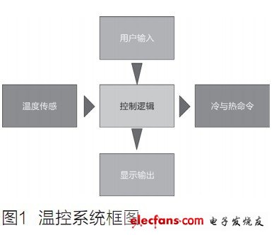
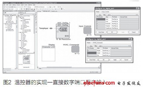
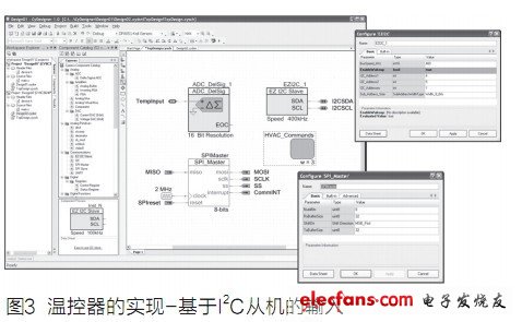
First, avoid MCU or programming language interference design As an experienced embedded system developer, both the experience of large systems (Boeing 777 flight control) and the experience of small single-person projects (laptop fan control) should avoid the specific advantages and disadvantages of a single machine or language. Spend more time on application design and build, and is independent of the language and CPU core. Part of this comes from working on similar systems, just "re-use" for the next project (though the requirements are completely different and switch to the microcontroller). I have also been involved in a system consisting of several separate devices, each with its own program and microcontroller, and each part is often used back and forth between different subprojects: the encoder in a subproject may be another A project's tester, or when you complete the coding of your own subproject, will invest in another subproject to help complete the project. The lack of a system-based design approach would make these situations difficult and difficult to accomplish as planned. Machine dependencies can be avoided through independent system design, making design reuse and team-based design not only possible, but also increasing opportunities for success (as required later). One of the more recent projects is that I am more skeptical, almost every time, the design must adapt (and sometimes simply) the language and machine of choice. We've started with a system architecture and design, but we've considered integrated microcontrollers and their peripherals in the usual way. We only focus on what we need and don't care how it's implemented, at least we think so. We chose some new devices with very specialized peripherals, and when we started coding, we found that it took a lot of time to understand how to build the hardware and how to best use it according to your needs. This feature of the device embeds a system-level design through code when we find a good way to take advantage of a feature of the device. We no longer insist on our system, we have to make the machine and the specific operation change the system design. So I had to stop and check the problem and implementation plan, separate the machine-repaired “repair†through the system redesign, and then integrate the “repair†into the “package†around the system. When designing an application (even a single microcontroller), taking the thermostat as an example, there is a created system-level view that describes the hardware and the application that implements some way. This view is used for a variety of purposes, for example, as a tool for communicating with top management or another group (not wanting to know all the details), such as automated testers. If you only think of it as a "view" rather than a system design, and the implementation is not from the top of the system design, but as a starting point, the problem arises. Consider the temperature control system shown in Figure 1.     The display system is relatively simple, but reflects many embedded product designs. The Temperature Sensing section contains a temperature input whose output enters the Control Logic section of the main system. The other input to the "Control Logic" is the part labeled "User Input", which represents the human interface, which is roughly the temperature adjustment of the thermostat. Based on these inputs, the Control Logic section determines how to command a heating, ventilation, and air conditioning (HVAC) system to maintain the thermostat set temperature and send these commands to the Hot and Cold Commands section. The last part is "display output", which passes the current system state to the user. Part of the current system state is the thermostat setting, the other part is the latest temperature reading, and the last part is the command being executed to force the temperature back to the thermostat setting (ie heating, cooling and/or turning the fan on or off). As mentioned earlier, this is a straightforward and relatively simple application, so simple that you don't need to think about the system, but naturally jump to implementation (I believe most readers can even say the favorite microcontroller vendor) Model). It can be a wall thermostat or temperature management device for high-end PC gaming graphics systems for the secondary market. The specific implementation of a microcontroller for a wall thermostat is basically not required for a graphics system. The point is that no matter how simple the design is, there are good reasons to design the system first and then implement it. Design it as much as possible for the usual application. To start with, you need to consider the ideal system design and then generate layers to build wrappers (sometimes messy) between the ideal system and the actual implementation. The "Control Logic" section is at the heart of the block diagram for good reason - because it is the kernel of the system. Each part around it serves the "Control Logic" section, providing "services" as needed. Start with the "Temperature Sensor" section. The reason is to obtain the current/instantaneous temperature and provide it in a consistent format. From the perspective of "control logic", its role is to "get temperature" and return the current temperature value with a formatted value (xxx.xx degrees Celsius). The hardware wrappers of the temperature sensor portion will include any Celsius in the implementation that is needed to "translate" the original temperature sensing input into the intended format. This may mean considering the best time to get a new reading. If there is too much noise in the temperature reading (for whatever reason), a filtering algorithm should be added, and if the temperature hardware fails, decision logic should be used. The point is, what is the output of the "Temperature Sensor" section, and the pass to the "Control Logic" should be the ideal temperature, all the noise, the actual hidden details should be easily replaced by the wrapper. What if the design needs to measure three temperature values ​​from three different points in the system (common for computers in a computer box)? Handling these three temperatures is a control logic problem (for example, when multiple outputs will also be controlled) If so, switching from 1 temperature to 3 temperatures means that the "Temperature Sensor" section is to be updated to provide 3 temperatures and wrappers created for each temperature implementation (allowing multiple types of inputs), then Control logic is also updated due to multiple outputs. This may mean three different "GetTemperature_n" services or need to update the service to determine which temperature parameter is identified. If the three temperatures are only used for weighting to get a "more realistic" system temperature, the control logic does not need to be changed. Simply enter the temperature sensing block containing the wrappers into the three temperatures in a uniform format and then pass a wrapper. These three temperatures are weighted to generate the single temperature required for the control logic. This approach is easy to include from different temperature inputs (eg, diode junction measurements for graphics processors and analog thermistors connected to the PCB) because wrappers isolate system logic from hardware. Let's validate this argument with two different implementation examples: one for the wall thermostat and the other for the temperature control subsystem on the graphics card. First, for the wall thermostat, as shown in Figure 2, assume that the 8051-based Cypress PSoC3 device is used. The hardware in the Temperature Sensor section consists of a thermistor connected to an ADC (16-bit delta-sigma converter). The hardware in the “User Input†section consists of five normally open button switches, one connected to the circuit ground and the other connected to a 5-input digital port with an internal pull-up resistor. The hardware portion of the "Hot and Cold Command" module consists of three power FETs driven by a 3-output port configured for open-drain low output. Finally, the hardware implementation of the "display output" block is a serial character liquid crystal display that can display alphanumeric strings as needed.     For the second application, the display card, the user input is changed from a discrete switch to an I2C register-based slave interface (directly controlled by the main CPU instead of the human) and the serial LCD display is changed to an SPI-slave control display (using A series of registers and instructions, possibly a remote frequency conversion display mounted on the front panel of the main computer housing, not mounted on the graphics card). The temperature input and HVAC commands remain unchanged. Figure 3 shows the changes in the early implementation, assuming an 8051-based Cypress PSoC3 device.     Both implementations of user input can serve "GetThermostatSetTIng", "IsHeaterEnabled", "IsCoolerEnabled", and "IsFanOn". For the first wall thermostat application, User Input wraps the digital port into the listed service and provides a real-time reading of the port (a possible implementation) when the device is called. For another application, based on the implementation of the I2C slave, the same service returns the most recent value from the register written by the I2C master to the "Control Logic" section, perhaps often returning perhaps only on power-up. And these implementations have many other features, including wall button switches used as toggle keys instead of instantaneous readings, and even edge-triggered asynchronous processing in the deeper layers of wrappers in the "user input" section. The key to the above is that the system design hides the hardware details; the hardware and implementation details are packaged and hidden by the system design. Through the implementation details of the external design (ie code), it is possible to protect these applications from splitting, to achieve personalized design, to weigh the pros and cons, to ensure successful project delivery, and to still provide reusability and group design. Don't let the seller draw attention – design the system first, then strengthen the protection system design implementation details without being plagiarized. ZOOKE provides you with safe and reliable connector products, with 1.0 spacing products providing more possibilities for limited space and creating more value for the research and development and production of terminal products. 1.00 wire to board connectors,1.0 connectors,ZOOKE connectors Zooke Connectors Co., Ltd. , https://www.zookeconnector.com
Read related series chapters
Detailed explanation of the key technology foundation of single chip microcomputer (1)
Detailed explanation of the key technology foundation of single chip microcomputer (2) 


Detailed explanation of the key technology foundation of single chip microcomputer (3)
SCM is widely used in industrial control, home appliances, consumer electronics, medical electronics, instrumentation and other fields. In response to the needs of the majority of junior electronic engineers / MCU enthusiasts, electronic enthusiasts plan and integrate the "Single-chip key technology basics" series of technical articles In the future, other chapters will be launched one after another. Please stay tuned and pay attention to the engineers and friends. The majority of engineers should respond enthusiastically to the first two chapters, and the electronic enthusiasts will continue to work hard to introduce more technical boutique articles for engineers to readers.