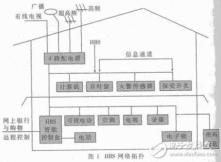
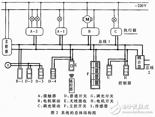
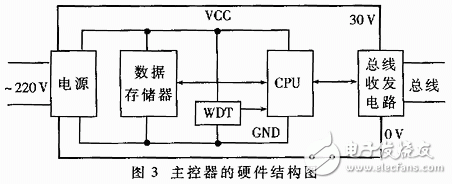
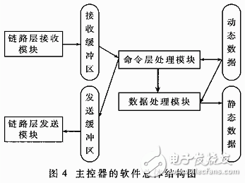
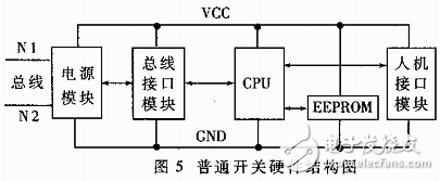
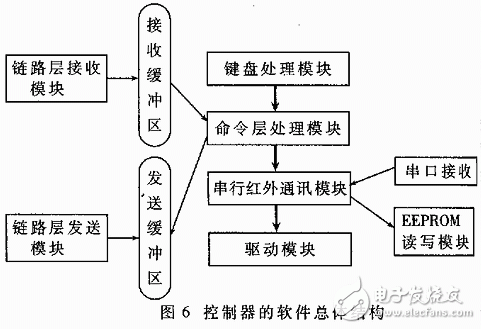
Since the completion of the first intelligent building in the United States in 1983, intelligence has become the mainstream technology for today's building development, from air conditioning systems, fire alarm systems to integrated security management systems (including closed-circuit monitoring, Security patrol, burglar alarm, access control system) and a complete computer network and communication system. At present, most buildings still use traditional lighting control methods. Some intelligent buildings use building automation (BA) systems to monitor lighting, but they can only implement simple area lighting and time switch functions, and can not flexibly manage lighting equipment with functions such as dimming and scene control. As far as the lighting system is concerned, it not only needs to control the lighting time and brightness of the lighting source to meet the needs of different applications, but also considers the management intelligence and the simplification of operation to meet the requirements of future lighting layout and control mode changes. The distributed intelligent lighting system based on HBS protocol developed by the author can meet the above requirements. 1 Introduction to HBS Protocol The full name of HBS is the Home Bus System, which was jointly proposed by some well-known Japanese companies, including Hitachi, Matsushita, Mitsubishi, Toshiba, etc., and got Japan. Government and Chamber of Commerce support. The network topology of the HBS is shown in Figure 1. The HBS protocol specifies how to interconnect home appliances, telephones, and audio-visual equipment over twisted pair or coaxial cable, with a focus on integrated automation of home appliances. At the same time, the HBS protocol also considers how to get remote services in the home, such as home shopping, telemedicine and distance learning. The protocol is mainly used for electrical switch quantity and simple analog quantity control. It adopts dedicated bus and has the characteristics of strong anti-interference, fast response, low development cost and low risk. 2 Intelligent lighting and security system working principle and performance indicators The main goal of intelligent lighting and security systems is to integrate the original discrete lighting appliances and security devices into an intelligent system through DC current-carrying bus technology for centralized or distributed, local or remote monitoring and control transactions. In this system, the transmission of information is of the utmost importance. The information mainly includes control commands and status responses. Any controller in the system can accept control commands from local or remote locations to change its state. After the controller status changes, a status response is issued, changing the status display of the local or remote location. Centralized or distributed, local or off-site monitoring, control, and transaction management are performed based on control instructions, targets, and the manner and timing of instructions. The overall structure of the distributed intelligent lighting and security system is shown in Figure 2. As can be seen from Figure 2, the distributed intelligent lighting system consists of three major components: the main controller, the controller and the actuator. The master is the controller of the system, responsible for the arbitration and transmission of the signals on the bus, and is responsible for the power supply of the bus. It is the core component of the system and each system must have a master unit. The controller is the input channel of the system information, the control command is issued by the user or the sensor, and the result of the execution of the control command is also displayed on the controller. At present, the controller basically appears in the form of buttons, including the common switch (Switch) (there are single button, double button, three button and four button specifications), dimmer switch (Dimmer Switch), motor switch (Motor Switch) wireless There are several types of receiver (Wireless Receiver) and master switch (Master Switch) (16~40 keys). There is also a telephone module for remote monitoring. The function of the wireless receiver is to forward the signal sent by the wireless remote control button to the bus. In addition, the sensor unit is also included in the controller part. The sensor unit of the non-type has different trigger conditions. Once the trigger condition is met, the sensor unit automatically issues a control command. The actuator is a specific drive unit, the information output channel of the system, which drives specific objects such as lights, power switches, warning lights, alarm bells, etc. according to control commands. At present, the system includes switch drivers (single-channel, dual-channel, four-channel specifications, which are responsible for driving the switch object, such as lamps, power sockets, electrical appliances, etc.), dimming drivers, and alarm drivers. The main functions of the system are: One-to-one control: one switch controls one light One-to-many control: one switch controls multiple lights at the same time Many-to-one control: multiple switches control one light Scene control: a switch allows multiple lights to reach a preset state Timing control: Provides on hold and off delay Status display: The status of the controlled light can be observed on the switch panel Infrared remote control: operate the light through the infrared remote control Security monitoring: anti-theft, gas leak, fire alarm remote monitoring by phone (voice prompt) The main technical indicators of the system are: Communication distance between network nodes is up to 600 meters Communication speed 4800 bits / sec The number of network communication nodes is up to 256 points. Network node programmable recordable Software check error function Supply voltage: DC 24V 3 main controller design 3.1 Hardware design of the main controller The hardware of the main controller is mainly composed of power supply, large-capacity data memory, CPU, WDT, bus transceiver circuit and other modules. The hardware structure of the main controller is shown in Figure 3. Since the CPU, WDT, RAM and other circuits work at the CMOS level, and the bus transceiver circuit has to handle the 24V voltage signal, the power supply is divided into two parts, respectively providing 5V and 30V voltages for the CPU and other modules and bus transceiver circuits. power supply. In order to reduce interference, a single-point grounding technique is adopted, that is, the ground wires of the two parts of the power supply are separately routed on the circuit board, and finally the two are connected at one point. The bus transceiver module is responsible for powering the bus and converting the signal level. It can convert the signal (0~5V) sent by the CPU into a bus voltage signal (0~24V), and can convert the current response signal sent back by the controller and the actuator into a CMOS voltage signal for processing by the CPU. 3.2 Software design of the main controller The main controller is mainly responsible for the static scanning and dynamic scanning of the system, maintaining and recording the status of the relevant address, and the binding and inclusion relationship between the controller and the actuator. The so-called inclusion relationship refers to which individual addresses or dimming addresses are included in a group address or scene address. Therefore, the main part of the main controller software is the processing of communication, the generation of commands and the maintenance of address status. Its overall structure is shown in Figure 4. The program is generally divided into command layer processing, link layer transceiver, data processing and other modules. The link layer transceiver module is responsible for sending the commands issued by the master controller into a data frame, and receiving responses and commands from the actuator and the controller, and sending them to the command layer for processing. The command layer is responsible for the processing of static and dynamic scans of the system, as well as the maintenance of system status. The data in the program is divided into two parts: dynamic data and static data. The static data is placed in the EEPROM, and the content is the address inclusion relationship, such as which individual or dimming address is included in the group address and the scene address. These contents are the control relationships set by the user and can be maintained after the system is powered off. The dynamic data is placed in the RAM, which is divided into two blocks. The state of each address when the system is running can be dynamically filled in by the runtime query; the other is the image of the static data, when the main controller is powered on. Read out from the EEPROM and fill it into RAM for query control relationship when the program runs. The control relationship of the system can be dynamically modified during operation. All modifications are first placed in the dynamic data area. When the user completes the modification, the image of the dynamic data area is rewritten back into the static data area, so that the new control relationship is saved. Come down. 4 controllers and actuators The hardware structure and software design of the controller and the actuator are basically similar, except that the actuator has one more drive module than the controller in hardware. The following takes the controller as an example. 4.1 Controller hardware design The controllers currently defined in the system include common switches (1 to 4 channels), dimmer switches, motor switches, wireless receivers, and main control switches (16 to 40 channels). Their hardware structure is basically the same, for example, the main control switch is composed of a plurality of ordinary switches and a set switch. The following is an introduction to the hardware design of the general opening. The hardware is mainly composed of four parts: power module, bus interface module, man-machine interface module and CPU module. The general switch hardware structure is shown in Figure 5. The power module will be fully rectified from the AC 24V introduced from the bus, converted into 24V pulsating DC power, and then passed through the voltage regulator circuit to output 5V voltage as the working power. Since the signal on the bus is AC 24V, which is much larger than the CMOS circuit level, level conversion is performed through the bus interface module, and then the signal is sent to the CPU module for processing. The loopback signal request is a current signal, and the output response after the CPU module is processed and processed is a voltage signal, so it is converted into a current signal by the bus interaction module, and then sent back to the bus. The human interface module is responsible for receiving user input, address settings, and status display by keyboard, LED, and infrared. The CPU module is the core of the entire switch and is responsible for receiving bus signals and user inputs, and then generating responsive actions and signals through operations, analysis and judgment. 4.2 Controller software design The whole software can be divided into five parts: keyboard processing module, command layer processing module, link layer transceiver module, serial infrared communication module and driver module. In addition, there are single support modules such as EEPROM read/write module and serial port receiving. The overall structure of the software is shown in Figure 6. The distributed intelligent lighting and security system based on HBS protocol adopts infrared addressing technology, which can combine control functions arbitrarily, with simple operation and intuitive interface. The 24V DC carrier bus technology makes the system easy to install and low in cost; Protection technology ensures that strong electrical faults will not affect the control system and improve the reliability of the system; low-power control technology is beneficial to extend the service life of the system and reduce the operating cost of the user; and the bus communication technology is reliable and Various types of function expansion modules are added, for example, remote monitoring by means of a PSTN-based telephone access module. Sliding Patch Panel,Sliding Patch Panel,Sliding Patch Panel Bracket,Sliding Patch Panel Box Huizhou Fibercan Industrial Co.Ltd , https://www.fibercan-network.com