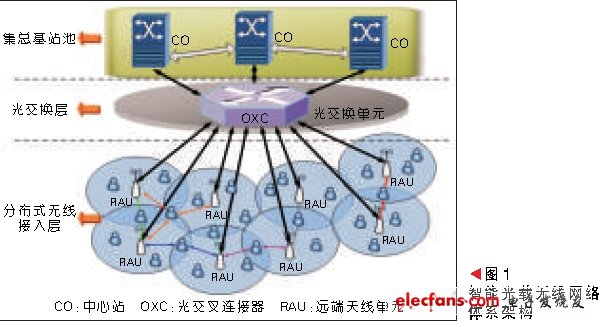
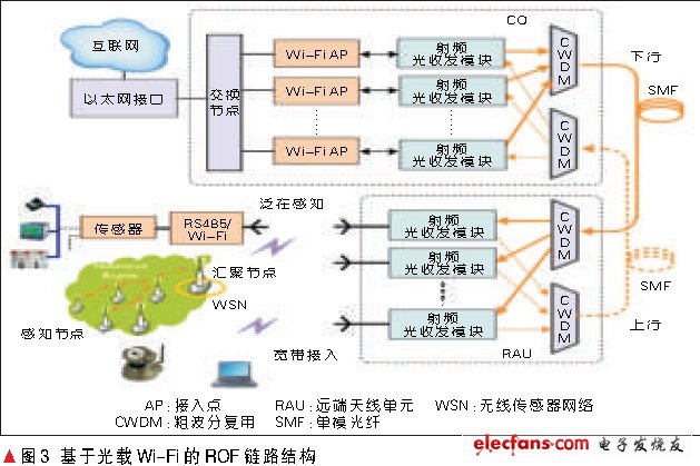
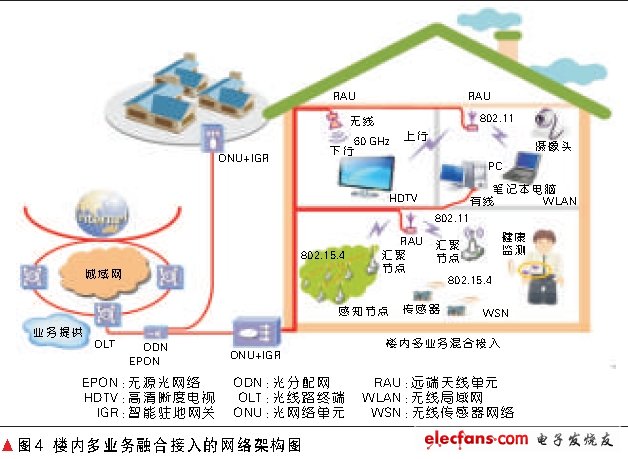
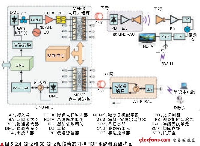
1 New network architecture To implement an intelligent optical-borne wireless network, designing a good network architecture is the first consideration. Combining the advantages of the current mainstream network architecture around the world and circumventing its shortcomings, we propose a fiber-optic radio (RoF) network architecture as shown in Figure 1. The architecture is divided into three layers, from bottom to top, the distributed wireless access layer, the optical switching layer, and the lumped base station pool. For the application requirements of a wide range of low-cost Wi-Fi coverage and the access requirements of high-data services such as Gigabit HD video in smart homes, we have embodied the above-mentioned general-purpose intelligent optical-borne wireless network architecture, and proposed two Specific scope of network architecture 1.1 Distributed optical Wi-Fi network architecture design and link implementation for broadband access and ubiquitous sensing applications The typical structure of the Internet of Things consists of three layers, namely the perception layer, the transport layer and the application layer [2]. This paper proposes a transport layer network based on the optical Wi-Fi heterogeneous structure. The network architecture is shown in Figure 2. The ROF link structure based on the optical Wi-Fi is shown in Figure 3. We use the analog direct modulation ROF network architecture based on the coarse wavelength division multiplexing (CWDM) method. After the analog direct modulation, the different wavelengths of light pass through the CWDM device. Multiplexed into one fiber for transmission, the other end of the fiber is demultiplexed by another, the optical signal is distributed to each remote antenna unit (RAU), the RF signal is recovered by the photodetector, and amplified by the antenna. Go out and achieve wireless coverage. The two-way link completion can meet the application requirements of broadband wireless access. The transparent structure is easy to upgrade, and it can meet the transmission of other wireless standard signals such as 3G with a small amount of hardware modification [3]. 1.2 Multi-band dynamic controllable ROF network architecture design and link implementation for multi-service converged access in the building Figure 4 is a diagram of the ROF network architecture for in-building multi-service converged access in the 2.4 GHz and 60 GHz bands. At the Optical Network Unit (ONU) of the Ethernet Passive Optical Network, an additional Intelligent Premises Gateway (IGR) is used to implement upconversion of baseband signals to 2.4 GHz and 60 GHz, as well as control and scheduling of RF resources, and Use indoor fiber optic network transmission. In order to solve the cost and technical problems in the uplink process, it is considered that uplink services such as video on demand (VOD) generally do not require a particularly high transmission rate. Here, through the terminal design and gateway processing functions, the existing Wi- in the adjacent room is utilized. The Fi signal is covered to meet the upstream demand for Gigabit downlink services. In this way, through the construction of the Wi-Fi distributed antenna system and the establishment of the Gigabit wireless communication link in the 60 GHz band, it is possible to provide Gigabit uncompressed high-definition television and its on-demand service, Wi-Fi signals, for users in the building. Broadband access and IoT services such as health monitoring, video surveillance and environmental monitoring enable the construction of intelligent and ubiquitous home networks. Figure 5 shows the transmission link of a dynamically controllable ROF network with multiple services in the building. Inside the ONU and the Intelligent Premises Gateway (IRG), the Gigabit HDTV service source in the Internet is provided to the building users via EPON in a wired manner. In order to support the wireless access mode, the Ethernet parallel data is serialized without using the conversion interface. The return-to-zero code is modulated onto a continuous optical carrier from a direct-tuning laser, and then a millimeter wave is generated using a Mach-Zehnder modulator (MZM) and transmitted through a millimeter-wave antenna. At the receiving end, the millimeter wave signal is received by the receiving antenna and amplified by power, and the down-conversion is performed by means of self-mixing, and finally the baseband signal can be obtained by filtering with a low-pass filter. In order to realize resource allocation, we propose a radio frequency switching technology based on microelectromechanical system (MEMS) optical switch matrix to realize the construction of dynamic controllable ROF network. In Figure 5, internally, the MEMS optical switch routing is controlled using commands from the central control unit. In this way, the use of the 60 GHz band and the 2.4 GHz band network, as well as the optical switch matrix, enables wireless intelligent coverage of multi-band multi-service in the building, greatly increasing spectrum efficiency and effectively reducing overall energy consumption.
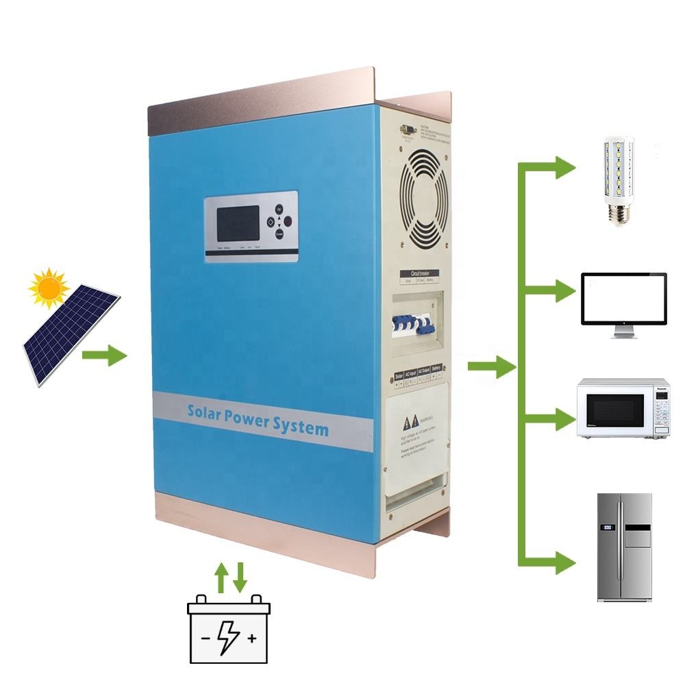
1KW-6KW Hybrid Inverter (with PWM Charge)
1KW-6KW PWM Hybrid Inverter,Lithium Battery Solar Inverter,AC 220V Solar Hybrid Inverter suzhou whaylan new energy technology co., ltd , https://www.nbwhaylan.com