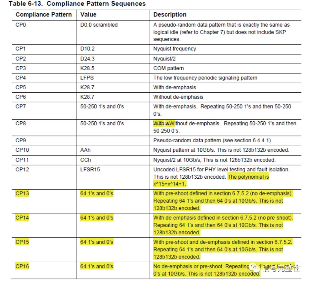
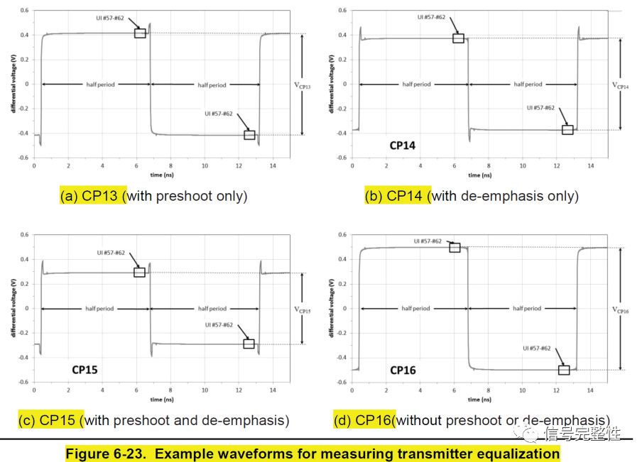
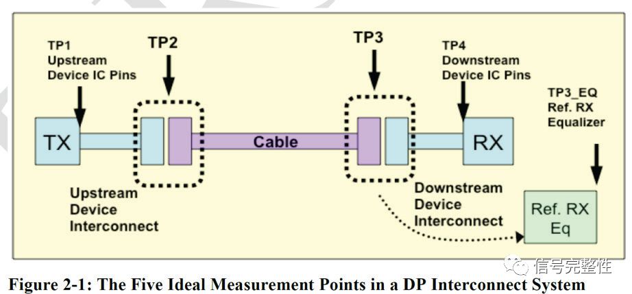
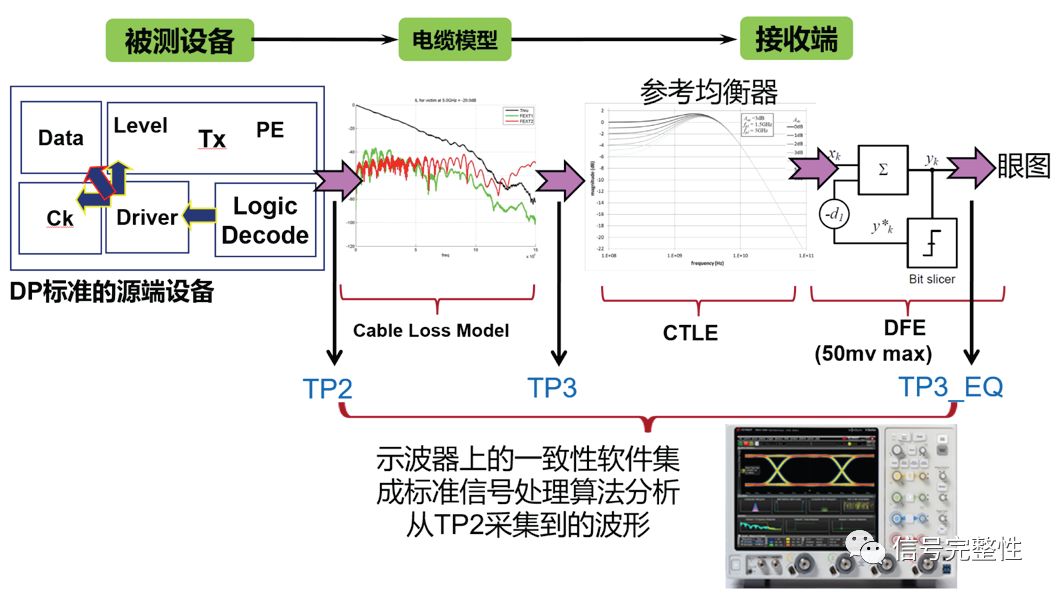
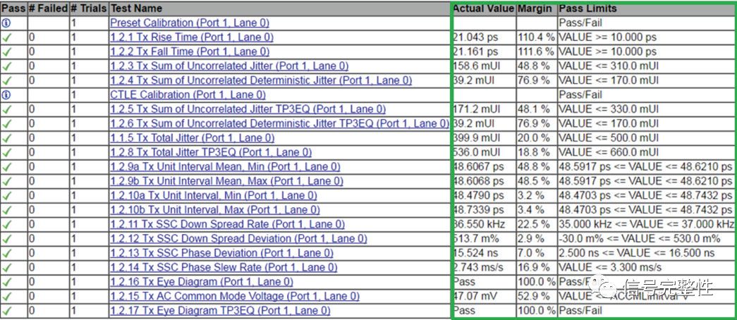
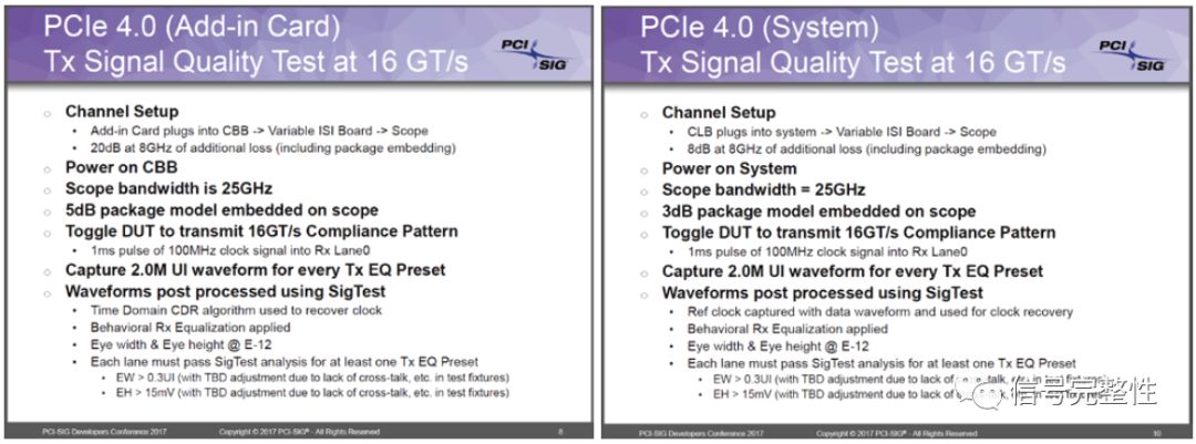
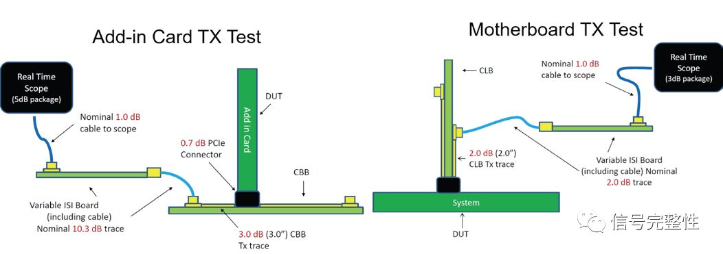
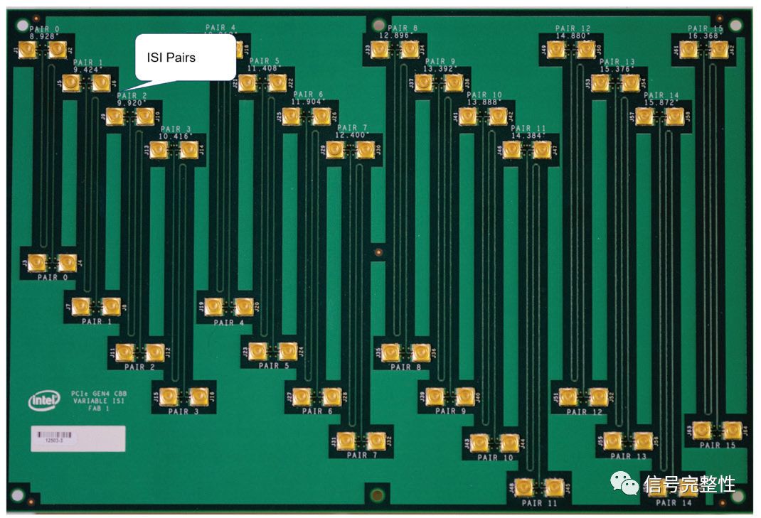
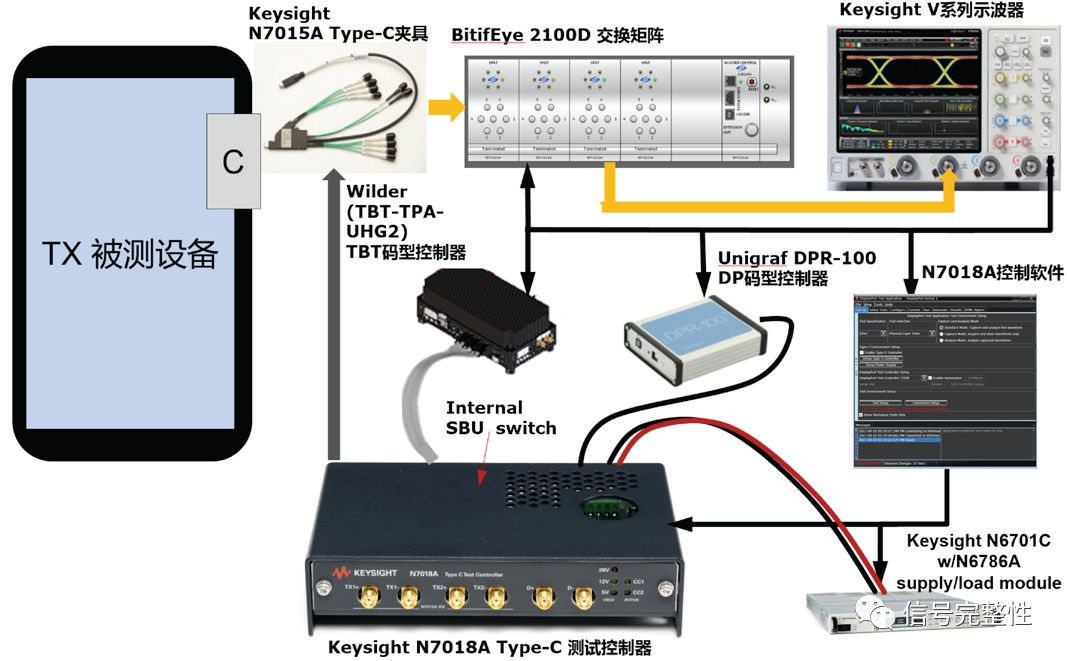
Physical layer conformance testing has been one of the most common uses of oscilloscopes for more than a decade. It has been one of the most commonly mentioned terms in the industry. This article attempts to make a simple discussion and description of the meaning, elements and purpose of the physical layer conformance test and future development trends. (Unless otherwise specified, compliance tests mentioned later in this article refer to physical layer conformance testing). The origin of conformance testing and what is conformance testing? The English word Compliance, widely used in various industries, is used in the electronics industry as its name implies. As the most familiar term for engineers in the industry, conformance testing has been in the hearts of people for more than ten years. The physical layer conformance test originally originated from the USB 2.0 standard and was popularized by the USB-IF Association and the industry giant Intel Corporation. Due to the sudden increase in the number of Hosts and devices and hubs using the USB 2.0 standard, the compatibility and disagreement of the physical layer and the protocol layer between devices need to be resolved. Therefore, a unified standardization has been established. The measurement method to evaluate the signal quality of each device. Conformance testing is similar to black box testing and usually focuses only on the signal quality at the external interface of the device. Through the conformity test approved by the association, you can use the corresponding logo. Today conformance testing has been widely adopted by major standards and protocols such as HDMI, DisplayPort, USB3.x, SATA/SAS, PCIExpress, ThunderBolt, and others. Another major organization in the industry, the IEEE, later introduced the concept of conformance testing on the 10/100/1000 BaseT test to evaluate the signal quality of each device. In fact, in any case, the USB2.0 and Ethernet are the two most successful and enduring interfaces and communication standards. Even in the recent 200G/400G standards published by the IEEE, similar test methods have been defined. So what exactly is conformance testing? What is its basis? Here, the author gives a superficial definition: the industry's universally accepted test for measuring the signal quality of a product using the same ruler to meet the standard, which is based on the conformance testing specification CTS (Compliance) defined by various standards and associations. Test Specification). By conducting conformance testing on the product, in addition to understanding whether the product meets the standard test specifications, it is also possible to quantify the margin of the signal's indicators from the CTS. If the margin is sufficient, it means that the product can be designed to reduce costs, and vice versa. For system manufacturers, in the face of rapidly changing markets and fierce competition, reducing product costs is a magic weapon for survival. For the upstream chip manufacturers, if the system based on its chip undergoes a conformance test, if it can show that there is a very high margin, it can show the performance of its products and provide sufficient confidence and leeway for the product design and development of its downstream customers. Quantity for cost-cutting design. Therefore, the importance of conformance testing for the entire industry is self-evident. With the development of digital technology and chip integration technology in recent years, electronic circuit debugging (Debug) accounts for a smaller proportion in the development of electronic products. Conformance testing is increasingly important as a part of the final shipment of products. The most important use of the oscilloscope. Conformance test meaning or element Conformance testing is so important. So what does it mean or what the definition given above contains for the same ruler? 1. Unified standard test signal This unified standard test signal, the English name is Compliance Pattern. From USB2.0 onwards, Intel developed a USBHSETTool for PC systems to send various signals such as Test Packet for eye diagram testing. The device under test that supports USB3.x standard has been developed to issue an IN packet after power-on. If an ACK packet is not detected, the Compliance test mode is entered and various Compliance Patterns are issued. The principle of the PCI Express standard is similar. There are special cases, such as display technology HDMI is not the same, Sink devices generally do not have high-speed signals back to the source, so you need to use an external EDID Emulator to deceive the source device has connected to a format of the Sink device, the source device will begin output signal. The DisplayPort standard and SATA standard usually need to modify the register configuration test pattern. Some standards also support the use of external controllers to automate the configuration of test patterns with software for conformance testing, such as the DP test controller developed by Unigraf and the Thunderbolt controller developed by Wilder. Why do you define a uniform test signal? Because different patterns are used for testing, the results obtained are also different. For example, using the 0101 pattern and using the 00110011 pattern, the resulting ISI jitter is definitely different. So in order to unify and standardize measurement, associations and standards organizations define standard test patterns. Currently the most typical is that the USB3.1 standard defines a number of different patterns for different test items: Table 1. USB3.x test pattern table The above-mentioned yellow-labeled pattern CP13-CP16 is a new pattern added to the USB3.1 specification for testing pre-de-emphasis or equalization on the transmitting side: Figure 1. USB3.1 CP13-CP16 Pattern Description 2. The standard connection method, usually a jig and cable combination In addition, in order to harmonize the testing environment, associations and standards organizations have also defined standard connection methods, usually using standard fixtures and cables developed by associations or third-party companies. Fixtures and cables are usually components that are introduced to facilitate the test connection. This will inevitably introduce test errors and reduce the system's test margin. Therefore, during the conformance testing process, the same test tool must be used to standardize the measurement to avoid test differences. Among the current mainstream standards, in addition to USB3.x and PCIE fixtures are still mainly provided by the Intel-led USB-IF and PCI-Sig association organizations, various other standard fixtures are provided by Wilder. In the test connection, the HDMI standard first needs to connect 3 pairs of data, and 1 tests the CLK at the same time. The SMA probe is connected to the oscilloscope and then connected to the oscilloscope for testing, so as to complete testing of all differential items at one time. In the definition of standards and specifications, several test points are generally defined. For example, TP1, TP2, TP3, and TP4.TP2 are defined in the USB 2.0 specification as typical Host test point locations, and TP3 is a typical test point for Device devices. position. Different standard defined test points have different meanings. For example, to the USB3.x standard, the TP1 defines the remote test point of the sending end, and the TP0 usually indicates that the sending end's near-end test point only serves as the Informative in the oscilloscope test software. test: Figure 2. Topology diagram of USB3.x test method In the past two years, after the signal rate continued to increase to more than 5Gbps, TPxEQ test points were usually introduced at the test points. For example, in the DP1.4 standard, the defined test point is TP3_EQ. This test point is usually characterized by the receiving system. The test point after the equalization algorithm is usually not detected in the actual test, and the equalization algorithm at the receiving end needs to be simulated in the conformance test software on the oscilloscope: Figure 3. DP1.4 test point definition and topology 3. Standard test algorithms and processes After the device under test issued a standard test pattern and connected to the oscilloscope through a fixture and cable, the oscilloscope is used as a receiver and the signal processing method of the analog chip receiver performs signal testing and analysis, in addition to the conventional measurement of the electrical characteristics of the signal. Eye diagrams and jitter analysis are also usually performed. The standard test algorithms mentioned in this article mainly refer to clock recovery and eye diagram and jitter analysis methods in early years, and are relatively simple. In recent years, technologies such as high-speed serial bus systems have been commonly introduced, embedded, and balanced, and signal analysis algorithms have been greatly improved. Typical external interface standards such as USB3.x/HDMI2.x/DP1.4 all need to test the remote eye diagram. In the actual connection, the signal is picked up by the fixture at the proximal end of the device under test and then embedded in the standard. The cable parameter model simulates the real transmission cable. This lossy cable parameter model brings about great attenuation to the signal. At the receiving end, an equalization algorithm (CTLE/FFE+DFE) must be used to recover the signal. Conformance testing software running on the oscilloscope will be fully embedded in the receiver's standard equalization algorithm to recover the signal and then perform various parameter analysis and eye diagram and jitter tests. Take the DP1.4 standard as an example: Figure 4 DP1.4 test functional block diagram It can be seen that in today's high-speed signal testing, the status and role of conformance testing software is increasingly important. Conformance test software in addition to the implementation of standard test algorithms to analyze and give test results, sometimes you can also make some configuration changes to debug test, that is, modify some test configuration parameters and options, called DebugMode. Conformance test software will sort all test results into reports after the test is completed. The report will specifically mark the margin level of each test item. For example, the KeThunderbolt N6470B test report is shown in the table below. The green box is divided into three columns. Displays measured values, margins, and Pass/Fail judgments: Table 2 Thunderbolt Conformance Test Software Results Report In fact, many interface standards such as PCIE, SATA, and USB3.x are used in today's Server, PC, and notebook industries. Intel, the industry-leading company, has also developed a special test software, Sigtest, that can perform post-data analysis. In the Sigtest software, different test script files (in the Template folder of the Sigtest installation folder) are defined for different standards and different test points. The standard conformance test software can also usually call DLL (dynamic link library) files in the Sigtest program to perform standard algorithm tests of leading companies in this industry. Due to the limited diversity and level of space and standards, this article no longer makes in-depth exploration and description of test algorithms. 4. Factors affecting the accuracy of conformance testing Earlier we described the meaning and nature of conformance testing. What exactly does conformance testing pursue? In the final analysis, there is margin (Margin). Its essence or ultimate motivation is to reduce costs. For system manufacturers, after the product design is completed, if the conformance test is conducted, it is found that the signal quality has a large margin from the requirements specified in the CTS specification, which means that the product can be designed for cost reduction, for example, the capacitance can be reduced. Or use cheaper connectors and even lower the number of PCB layers, all of which seem to be a small cost reduction consideration, will be amplified in large-scale mass production, which will bring considerable economic benefits. Of course, cost-reduction design is not a bottom line. The bottom line is CTS. Therefore, many manufacturers in the industry sometimes design and test the product repeatedly to find the final balance point. The oscilloscope plays an important role in this process. For chip or upstream manufacturers in the industry chain, after the product design is completed, a reference design is also required and conformance testing is performed to submit reports to downstream manufacturers to prove the high quality and margin of their products and to give their customers enough Confidence is designed for cost reduction. Test measurement process will inevitably bring error, then how to minimize the error or get the highest Margin? In addition to the three points we discussed earlier, to ensure proper conformance testing, it must be considered from the equipment side. The first is to choose the right oscilloscope. Some oscilloscope indicators such as bandwidth, sampling rate, noise floor and jitter will affect the compliance test margin. The bandwidth is a familiar indicator for many people. The sine wave 3-5 is often referred to as the bandwidth and the bandwidth of the 9-fold frequency of the square wave. For the general high-speed serial bus data (NRZ encoding), a kind of NRZ encoding is used in the past. Speed ​​algorithm: signal frequency/2*5, such as 5GBps NRZ signal, the fundamental frequency is 2.5GHz, 2.5GHz*5=12.5GHz or more can be used. In addition, it is more accurate to calculate the bandwidth based on the rising edge time of the measured signal, usually 20%-80% rising edge time, the signal frequency Bw=0.4/Tr, and the recommended oscilloscope bandwidth is multiplied by a factor of about 1.4 to 1.8. . Bandwidth can not meet the test requirements will directly reduce the amplitude of the signal directly affect the eye height amplitude and the rising edge of the accurate test. In recent years, with the development of technology and the introduction of equalization, this rule has also changed. For example, for PCIE4.0 16.0Gbps, the recommended cutoff bandwidth for CTLE and de-embedding given in the PCIE4.0 specification is 20GHz in order to prevent de-embedding to excessively amplify the instrument's noise floor: Table 3 Recommended cut-off cut-off frequencies for the PCIE 4.0 specification On the other hand, for signal source calibration during RX testing To ensure accurate alignment of the edges of the BERT output signal, an oscilloscope with a 25 GHz bandwidth is recommended in the specification for testing: Considering both, the recommended bandwidth for PCIE 4.0 in the CEM test is 25GHz: Figure 5 PCIE4.0 Compliance Updates About Conformance Test Bandwidth Description The sampling rate is another important indicator of the oscilloscope. For today's digital real-time oscilloscopes, the sampling rate must be 2.5 times the bandwidth of the oscilloscope to ensure accurate signal recovery. Although the Nyquist sampling theorem indicates that 2 times sampling can restore the signal, the signal targeted by the Nyquist theorem is a sine wave, and today's measured signals are mostly high-speed digital signals. The other two relatively obvious indicators that have a significant impact are the oscilloscope's noise floor and jitter. The influence of the inherent jitter of the oscilloscope on the eye diagram test is similar, and it will inevitably increase the error of the jitter-related item test. Since the equalization and de-embedding both compensate the signal in the direction of the vertical amplitude of the signal, the effects and influences that are superimposed on the intrinsic jitter require a rigorous quantitative analysis of mathematical operations. For the HDMI interface that also needs to use the probe for testing, when the probe is connected to the signal, it will only enter the front end of the oscilloscope and sample the ADC due to its inherent attenuation characteristics. The oscilloscope will amplify the signal and also amplify the noise floor. Therefore, the attenuation factor of the probe is also one of the factors that affect the accuracy and margin of the consistency test. The effect of the oscilloscope's noise floor on the eye-diagram test can be found in the reference "On the Significance of Oscilloscope Low-Noise Noise for High-Speed ​​Eye Diagram Testing." The trend of conformance testing Finally, talk about the development trend of conformance testing. As an important part of product shipments, conformance testing plays such an important role in today's product development and manufacturing, and will inevitably bring about huge workload and burden. Therefore, from the initial hundreds of MBps-class USB 2.0 and Ethernet 10/100/1000 BaseT to today's tens of Gbps high-speed serial data standards, the trend has been toward simpler, more standardized, and more automated. The ultimate goal The purpose is to reduce the complexity of the test and increase production efficiency. More simple, mainly reflected in the output of the test pattern. As previously discussed, from the initial need for specialized outbound software or change registers to output test signals to today's Built-in BIST (Built in Self-Test Pattern) test pattern, it is currently implemented on both PCIEXpress and USB3.x. On the DisplayPort and Thunderbolt standards, there are special test pattern controllers developed by third parties, such as the DP controller provided by Unigraf and the Thunderbolt controller provided by Wilder. More standardized, reflected in the definition of the test connection. For example, in the definition of the USB3.0 test method, it was initially defined to use a physical cable approved by the Association to simulate a remote test point, but since the physical cable is still different, the S-parameter model was later used instead of the physical cable, which completely eliminated Differences in different connection environments. This method is also used today in HDMI2.0/DP1.4. In the PCIE 4.0 specification, a similar method is used, but instead of a software S-parameter model, an ISI fixture board provided by the Institute is used to simulate the entire link. Take the CEMAdd-inCard TX test as an example. The ISI fixture board is used to simulate an additional standard 20dB @ 8GHz loss: Figure 6 Block Diagram of PCIE4.0 CEM Test Figure 7 PCIE4.0 CEM ISI Fixture Board This hardware ISI fixture is sold by the PCI-Sig Association and is unique and standard. Whether it will be implemented in the future using the S-parameter model of the software does not rule out this possibility. The last trend is the growing demand for test automation. Due to the complexity of various standards and interfaces, it brings many problems for consumers to use, and at the same time, it also aggravates the complexity of R&D design and testing. Therefore, the industry is working hard to promote the use of a unique Type-C interface. Standards such as USB, DP, HDMI, and Thunderbolt all support this interface. The following is a complete test plan: Figure 8 Type-C interface test plan As shown above, using the N7015A Type-C fixture and N7018A controller, with the switch matrix, after completing all connections, the N7018A control software running on the oscilloscope will automatically set the Type-C Alt Mode, switching the Type-C interface to USB, DP In the TBT mode, the N7018A controller can output LFPS signaling, configure the DUT to send USB3.x standard test patterns, and Thunderbolt and DP require Wilder and Unigraf controller configuration test patterns, respectively. The measured signal is connected from the N7015A fixture to the switch matrix and then connected to the oscilloscope. The oscilloscope controls the switch matrix through the network port to switch the signals of different links to the oscilloscope. If you need to test different devices under test, just connect the device to the N7015 fixture. to sum up This article discusses the meaning, elements, goals, and trends of the physical layer conformance test at the sending end. It is impossible to elaborate on many details in terms of space. In addition to the sending end, in recent years, the consistency test at the receiving end has also become a test content that various standards must consider as the signal rate increases rapidly. Please pay attention to more discussion and sharing. Anti-Jamming RC Arc Extinguisher
Anti-Jamming RC Arc Extinguisher
Anti-Jamming RC Arc Extinguisher YANGZHOU POSITIONING TECH CO., LTD. , https://www.cnchipmicro.com