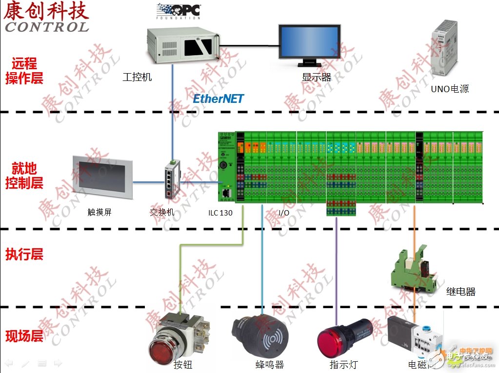
1. The control box is connected to a power supply of 220VAC, and there are air circuit breakers, PLC controllers, relays, switching power supplies, and 220VAV to 220VDC power modules in the control box. The 220VDC power supply is connected to the junction box to provide power for the solenoid valve. 2. The 24VDC power supply in the control box provides the signal power for the solenoid valve to open and close. 3. The status of the solenoid valve is uploaded to the top PC through the PLC Ethernet port, and the top PC can also control the solenoid valve to open and close at the same time. 4. The control box can independently open/close a single solenoid valve and display status information. 5. When the solenoid valve is abnormal, the PLC will output a sound and light alarm. 6. The control box has an "emergency control" button. When this button is pressed, the pneumatic control box is self-locking. The top PC can control the solenoid valve switch, this button has a protective cover. 7. The control box has a "reset" button, resets the "emergency control" light, self-locking cancellation, and a single switch can operate the solenoid valve. 8. There is an "experiment" button on the control box to detect the indicator light and buzzer on the control box. 9. There is an "unlock" switch on the control box. When unlocked, the operation of the operation panel is valid. Wire to Board Connrctor|Board to board connector|Floating connector|Power connector|Power supply plus signal connector|Slot connector Dongguan SOLEPIN Electronics Co., Ltd , https://www.wentae.com
Introduction to Phoenix PLC Control Cabinet System Design
Function Description