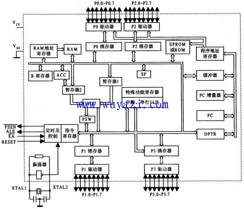
1.MCS-51 microcontroller internal structure block diagram We make OBD connector with terminal by ourselves,
soldering type and crimping type are both available. Also 12V and 24V
type. OBD1, OB2, J1939, J1708, J1962, etc. Also molded by different
type, straight type or right-angle type. The OBD connector cables used
for Audi, Honda, Toyota, BWM, etc. We have wide range of materials
source , also we can support customers to make a customized one to
replace the original ones. Sae J1708 Connector,Sae J1939 Connector,OBD2 Diagnostic Connectors,Diagnostic Connector,Deutsch Diagnostic Connector ETOP WIREHARNESS LIMITED , https://www.oemwireharness.com
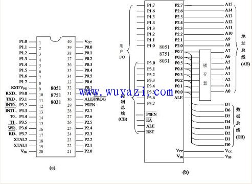
2.MCS-51 pin diagram 
3. Pin introduction
VCC (40 feet): Connect the +5 V power supply positive terminal.
VSS (20 feet): Connect to the +5 V power supply ground.
XTAL1 (19 feet): Connect one end of the external quartz crystal. Inside the microcontroller, it is the input to an inverting amplifier that forms the on-chip oscillator. When an external clock is used, this pin is grounded for HMOS microcontrollers; for CHMOS microcontrollers, this pin acts as an input for the external oscillator signal.
P0 port (39~32 feet): P0.0~P0.7 are collectively referred to as P0 port. It can be used as a quasi-bidirectional input/output port when the off-chip memory is not connected and the I/O port is not extended. When an off-chip memory or an expansion I/O port is connected, the P0 port is time-multiplexed into a lower 8-bit address bus and a bidirectional data bus.
P1 port (1~8 feet): P1.0~P1.7 are collectively referred to as P1 port, which can be used as quasi-bidirectional I/O port. For the 52 sub-series, P1.0 and P1.1 have a second function: P1.0 can be used as the count pulse input terminal T2 of the timer/counter 2, and P1.1 can be used as the external control of the timer/counter 2. End T2EX.
P2 port (21~28 feet): P2.0~P2.7 are collectively referred to as P2 port, generally can be used as quasi-bidirectional I/O port; connected with off-chip memory or extended I/O port and addressing range exceeding 256 In bytes, the P2 port is used as the upper 8-bit address bus.
P3 port (10~17 feet): P3.0~P3.7 are collectively referred to as P3 port. In addition to being used as a quasi-bidirectional I/O port, each bit can be used for the second function, and each pin of the P3 port can be independently defined as the input/output or the second function of the first function. The second function of the P3 port is shown in Table 2.1. 