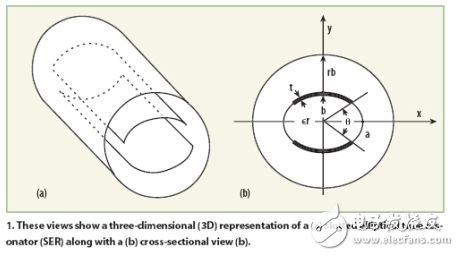
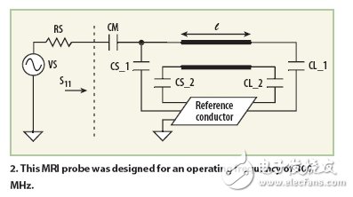
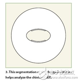
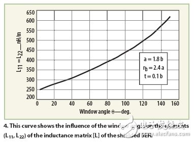
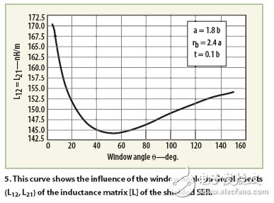
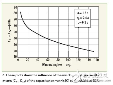
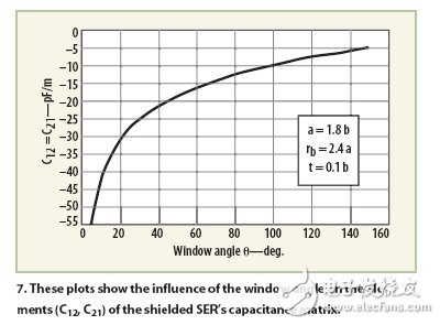
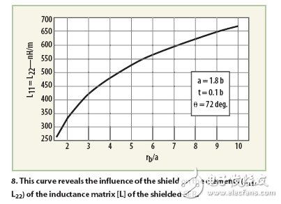
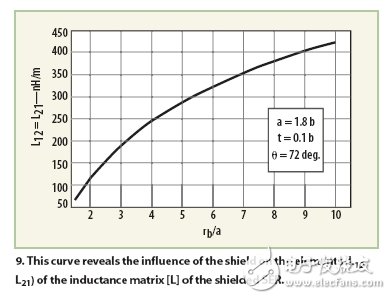
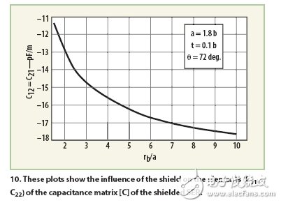
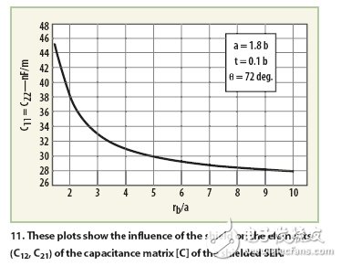
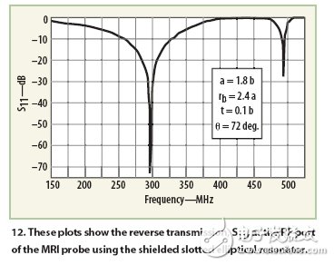
The Magnetic Resonance Imaging System (MRI) captures high-resolution human profile perspectives and provides very useful information for medical problems. The RF probe is an important component of the MRI system. It emits a uniform RF magnetic field and receives magnetic resonance signals reflected from the human body to restore high quality images. This paper describes an electromagnetic analysis of a magnetic resonance imaging system probe. There are many RF probes for MRI systems. In order to improve the fill factor and improve the signal-to-noise ratio, people are paying more and more attention to the research of non-column coils. Ellipsoid coils are ideal for outpatient applications (such as wrist or abdomen diagnosis). This type of coil is also suitable for non-medical applications (such as analyzing food inside the package). This kind of coil is not only complicated in theoretical analysis but also difficult to implement in practice. It is necessary to use birdcage analysis. Document 3 proposes a simple and efficient elliptical slot oscillator for replacing elliptical bird cage coils. It is shown by finite element numerical calculations (partially considering the shielding effect) that the field uniformity of the elliptical slot oscillator is the same as that of the non-columnar bird cage coil, and has the advantage of being easy to manufacture and operate. The author uses transient analysis to perform two-dimensional electromagnetic analysis of an empty elliptical slot oscillator. The analysis can derive the electromagnetic parameters of the oscillator: the [L] and [C] matrices, and the RF port frequency response S11 of the design is simulated taking into account all geometric parameters. In order to demonstrate the performance of the SER in practical applications, the resonator is used in an optimally configured MRI system. As an RF probe, the system operates at 300 MHz (neutron imaging), which exhibits -73.27 dB. The minimum reflection has a no-load quality factor of 500. 1 is an equivalent circuit diagram of an elliptical slotted oscillator. The coil is composed of two conductor plates of thickness t, and the two plates are located on both sides of the cylinder, respectively, and have opposite currents. The two conductor plates can be mounted on the long axis (a) or the short axis (b) of the ellipse. The literature 3 calculates by finite element analysis that the corresponding uniformity of the field of the conductor plate on the short axis is better. The bottom of the conductor plate is connected by a capacitor. Figure 1b is a cross-sectional view of the elliptical slot oscillator, the angle θ is called the "window angle", the optimum value of the window angle and the long axis-minor axis ratio (a/b) of the elliptical shell and the outer radius. - The long axis ratio is related to (rb/a). The SER of the three analyses of the literature has a/b=1.8, rb/a=2.4, and the best field uniformity is achieved when the window angle is 72 degrees. The electromagnetic properties of the shielded no-load SER can be characterized by the following main parameters: inductance matrix [L], capacitance matrix [C]; and its secondary parameters: no-load quality factor Qo. In the inductance matrix [L]: The diagonal elements represent the self-inductance of the conductor plates, and the non-diagonal elements represent the mutual inductance between the conductor plates. The capacitance matrix [C] represents the capacitive effect between the two conductor plates, which together represent the electromagnetic energy stored by the shielded SER. In this paper, the LINPAR Multi-Conductor Transmission Lines program is used to calculate the inductance matrix [L] and the capacitance matrix [C]. The software uses the MoM (Method of Moments) calculation. A quasi-static matrix of multi-conductor transmission lines in a segment isotropic medium. The method used by the software is based on static electromagnetic analysis. In the analysis, the dielectric is replaced by the bound charge in the vacuum, and the conductor is replaced with a free charge. According to the ordinary component of the electromagnetic field and the charge distribution considering the boundary conditions, a set of integral equations is obtained. The MoM method is used to solve the set of equations. The piecewise constant approximation and Galerkin technique are used for the total charge distribution. Once the [L] and [C] matrices are obtained, the modified digital model can be used to estimate the resonant spectrum of the oscillator (S11), as shown in Figure 2. The NMR probe consists of a shielded SER oscillator with a length of l, a matching capacitor of CM, and a termination capacitor of CSi and CLi (i = 1, 2). The oscillator no-load quality factor Qo can be estimated by sweeping the reflection coefficient S11. Where: fr = resonant frequency; fu = compared with the resonant point, the response changes by 3dB corresponding to the higher frequency; fl = compared with the resonant point, the response changes by 3dB corresponding to the frequency, the lower frequency . The MoM method makes it possible to simulate and decide whether or not the probe can be implemented. Figure 3 is a schematic diagram of splitting the surface charge of a shielded SER using the LINPAR program. Figures 4, 5, 6, and 7 illustrate the effect of the window angle θ on the electromagnetic parameters [L] and [C]. The effect of the shield on the electromagnetic parameters is shown in Figures 8, 9, 10, and 11. The [L] and [C] matrices of SER taking into account various geometric parameters can be derived by the MoM method. These resulting figures help to design probes for nuclear magnetic resonance systems. For the case of rb/a=2.4 and θ=72 deg, the electromagnetic parameters of the SER are as follows: The final design parameters of the MRI probe depicted in Figure 2 are as follows: The short axis b is 10 cm; The long axis to short axis ratio (a/b) is 1.8; The outer radius-long axis ratio (rb/a) is 2.4; Conductor thickness - short axis ratio (t / b) is 0.1; The window angle θ is 72 degrees; The relative dielectric constant εr is 1; Oscillator length l 25cm; The matching capacitor CM is 20pF, and the source and load termination capacitors CSi and CLi are both 1pF. Figure 12 is a simulation of the reflection coefficient S11 of the RF probe port. The probe using the shielded SER has a minimum reflection coefficient at a resonance frequency of 300 MHz. In summary, this paper provides a method for implementing a nuclear magnetic resonance system probe using a shielded elliptical slot oscillator. In order to achieve the final design effect, it is necessary to obtain various electromagnetic parameters of the shielded SER. The quasi-static electromagnetic parameters [L] and [C] of the oscillator are calculated using the LINPAR two-dimensional electromagnetic simulation software based on the MoM method in the frequency range of 150 to 520-MHz. After obtaining the main inductance matrix [L] and the capacitance matrix [C], the frequency response S11 of the RF probe port can be estimated, and then the no-load quality factor Qo can be obtained. 9H Flexible Glass Screen Protector
This kind of Flexible Glass Screen Protective Film is made of nano-glass material and is an indispensable device for people who often drop their mobile phones. The Flexible Protective Film can be perfectly fixed on the mobile phone to completely protect the mobile phone screen to prevent scratches and cracks on the edge of the mobile phone screen.
The surface hardness is 9H hardness. Sharp objects (such as knives and keys) will not scratch the surface.
The high transparency of 0.22mm ensures that you can view all screen content clearly and clearly, while providing unique touch screen sensitivity.
The Screen Protection Film has an "oleophobic and waterproof" coating that prevents dust and fingerprint smudges and ensures that it can be easily removed.
In case the screen is damaged, the Screen Protector will break into small pieces that are not sharp, which is much safer than other glass screen protectors on the market.
If you want to know more about 9H Flexible Glass Screen Protector products, please click product details to view the parameters, models, pictures, prices and other information about 9H Flexible Glass Screen Protector products.
Whether you are a group or an individual, we will try our best to provide you with accurate and comprehensive information about 9H Flexible Glass Screen Protector!
9H Flexible Glass Screen Protector, 9H Screen Protector, 9H Flexible Protective Film, Flexible Protective Film Shenzhen Jianjiantong Technology Co., Ltd. , https://www.hydrogelprotectivefilm.com