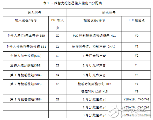
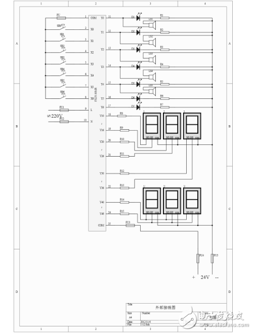
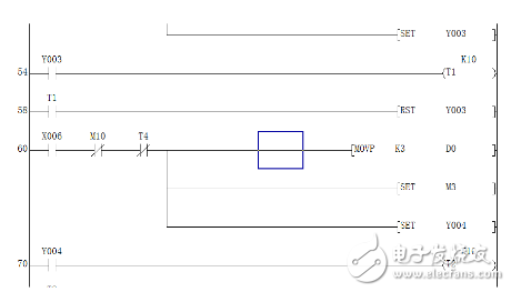
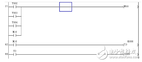
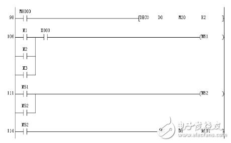
In the knowledge contest, cultural and recreational activities (competition events), the seat number of the respondent can be accurately, fairly and intuitively determined. Better promote the sense of competition of various groups, let the players experience the pressure of the battlefield. The traditional responder only judges the success or foul player number, and can't show the time of each player's answer. Now the responder can use data to explain the accuracy and fairness of the ruling results. The game has greatly increased the entertainment, but also more fair and just. The addition of wireless responders is a major reform in the history of responders. 1. After pressing the start button (starting to answer), if no one answers within 10s, the responder will automatically cancel the answer signal (with an audible prompt), indicating that the question is unanswered and automatically invalidated. 2. After pressing the start button (starting to answer), the first button press signal is valid, the remaining signals (post pressed) are invalid, and the valid signal is indicated by light and sound. 3. If someone answers, press any of the answer buttons, and start timing by pressing the button. When the answer time (about 1 minute) is completed, there are lights and sound signals to remind the answer time. 4. The three-way responder should have a light display and a minute value display. If the answer is correct or incorrect, under the control of the operator, 10 points or 10 points can be added. The maximum score for bonus points is 99 points, and the minimum score for score reduction is 00 points. The workflow is shown below. The I/O address assignment of the PLC according to the mission requirements and selected FX3U-80MR (considering 20% ​​interface margin) and other hardware (buzzer, lamp, seven-segment digital display tube) is shown in Table 1. According to the requirements of the topic and the I/O address assignment, six common cathode digital tubes are selected. The wiring diagram of the PLC external system combined with the FX3U-80MR is shown in the figure below. In order to facilitate the wiring of the hardware circuit, the start button of the SB1 is answered, and the corresponding input point is the X1 output point is Y0. SB1, SB2, and SB3 correspond to three entry pairs, respectively, and the input points are X4, X5, and X6, respectively, and the output points are Y2, Y3, and Y4, respectively. SB0 is the reset button of the answer, and the corresponding input point is X0. The digital tube 1 displays the output point as Y10-Y16. The digital tube 2 displays the output point as Y20-Y26. The digital tube 3 displays the output point as Y30-Y36. The PLC and the digital tube are directly connected by a series resistor. In order to simplify the programming structure and clarify the intermediate relays in the main program, X4—X6 are the answer signals of the three groups of players respectively. At the same time, we use the intermediate relays M1, M2, M3, M10, M51, M52 for self-locking and interlocking. Features to ensure that each player is fairly responsive. The host console has an X1 button for the answer and the X0 button for the reset button. When the start button SB1 is pressed, all data registers are reset (except for the accumulated score data registers D1—D4), then the three groups of responders start to answer, and the cut-off signal also generates a cut-off signal M10 (the latter is invalid). The answer time is 60 seconds. After the answer, the host starts adding and subtracting points (generating a strobe signal based on the answer). The group that does not answer the question can't add or can't see the score. It is necessary to judge D1 - D4 while adding or subtracting points (you can use CMP instruction or LD =). If it is over 99 or below 0, it will be treated with 0 When the moderator presses the grab start button X1, it resets D0 and M52. At the same time, there is a grab start sound signal Y1, and D1_D4 is reset when the PLC starts running. As shown below. Initial reset When the responder presses the answer, X4 (or X5, X6) is ON, and an interlock signal M10 is generated (locking other players to answer). At the same time, Y2 (or Y3, Y4) has an ON signal for 1 second. The program for setting M1 (or M2, M3) for later program selection is shown in the figure below. Answer procedure Answer procedure According to the task requirements, if no answer is answered within 10 seconds, the answer signal will be cancelled (implemented by T4). The program is shown below. Unattended procedure Timing is started using intermediate relays M10 and Y2 and Y3 and Y4. If you have already answered the question, the time for answering the question will be 60 seconds. If you have 60 seconds, you will not be allowed to answer the question. The program is shown below. Answer timing program Initially, it is necessary to decode D0 as the addition and subtraction strobe signal, and at the same time, the responder's signal (M1, M2, M3) participates in the selection of addition and subtraction. The program is shown below. Addition and subtraction initialization procedure If the answer is correct by 10 points, the error is reduced by 10 points. If the bonus is more than 99 points or the score is less than 0, the zero processing is performed. At the same time, considering that the single digit is always zero, the same output interface is used to connect the digital tube. Direct addition and subtraction of ten. The procedure is as shown below. Addition and subtraction procedure Litecoin (LTC) is a cryptocurrency created as a fork of Bitcoin in 2011. It uses a hashing algorithm called Scrypt that requires specifically designed mining software and hardware. It is minable, and continues to rank in the top cryptocurrencies for value and trading volume. Ltc Asic Miner,Antminer L3 Plus Plus,Bitmain Antminer L3 Plus,Bitmain L3 Plus Shenzhen YLHM Technology Co., Ltd. , https://www.ylhm-tech.com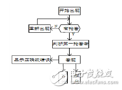

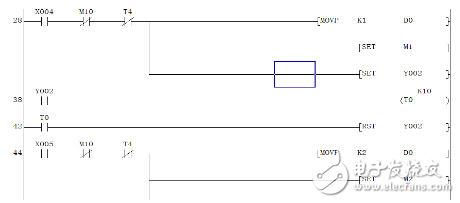

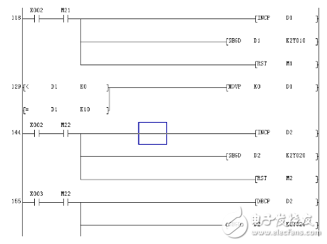
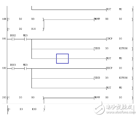
Addition and subtraction procedure
Litecoin mining is the process of validating transactions in the blockchain, closing the block, and opening a new one. Litecoin uses the proof-of-work consensus mechanism, which uses computational power to solve the nonce, which is part of the hash, that secures the block. The hash is the alphanumeric sequence of numbers that is encrypted by the hashing algorithm. When the nonce is solved, Litecoin is rewarded.
Litecoin mining became popular in 2011 when Charlie Lee, a software engineer at Google, announced its creation as a Bitcoin fork with modifications intended to help it scale more effectively.
Just like Bitcoin, it can be mined on computers using central processing units and graphics processing units. However, it isn't as profitable or competitive as purchasing an application-specific integrated circuit (ASIC) and joining a mining pool.