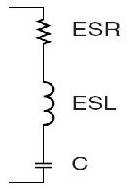
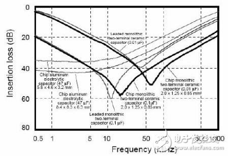
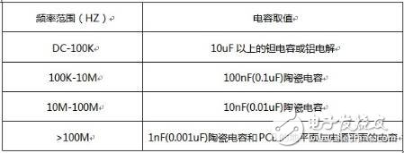
We can see a variety of capacitors on the power supply filter circuit, 100uF, 10uF, 100nF, 10nF different capacitance values, then how are these parameters determined? Don't tell me to copy other people's schematics, huh, huh. The digital circuit must be stable and reliable, the power supply must be “cleanâ€, and the energy supplement must be timely, that is, the filter decoupling must be good. What is filter decoupling? Simply put, the energy is stored when the chip does not need current. When you need current, I can replenish energy in time. Don't tell me that this responsibility is not DCDC, LDO, yes, they can be done at low frequencies, but the high-speed digital system is different. Let's take a look at the capacitor. The function of the capacitor is simply to store the charge. We all know that capacitor filtering is required in the power supply, and a 0.1uF capacitor is decoupled at the power supply of each chip. Wait, how do I see that the capacitance next to the power pin of some board chips is 0.1uF or 0.01uF, what is it? To understand this path, we must understand the actual characteristics of the capacitor. The ideal capacitor is just a charge memory, C. The actual fabricated capacitor is not so simple. The capacitor model we used when analyzing the power integrity is shown in the figure below. In the figure, ESR is the series equivalent resistance of the capacitor, ESL is the series equivalent inductance of the capacitor, and C is the true ideal capacitor. ESR and ESL are determined by the manufacturing process and materials of the capacitor and cannot be eliminated. What are the effects of these two things on the circuit. ESR affects the ripple of the power supply, and ESL affects the filter frequency characteristics of the capacitor. We know that the capacitance of the capacitor is Zc=1/ωC, the inductance of the inductor is Zl=ωL, (ω=2Ï€f), and the complex impedance of the actual capacitor is Z=ESR+jωL-1/jωC= ESR+j2Ï€f L-1/j2Ï€f C. It can be seen that when the frequency is very low, the capacitor acts, and when the frequency is high, the effect of the inductor cannot be ignored. When the frequency is high, the inductor plays a leading role. The capacitor loses its filtering effect. So remember that the capacitor is not a simple capacitor at high frequencies. The actual capacitor filter curve is shown below. It is said that the equivalent series inductance of the capacitor is determined by the manufacturing process and material of the capacitor. The ESL of the actual chip ceramic capacitor is from a few nH to a few nH, and the smaller the package, the smaller the ESL. From the filter curve of the capacitor above, we also see that it is not flat. It is like a 'V', which means that there is a frequency selection characteristic. At that time, we hope that it is as flat as possible (pre-stage board-level filtering). And sometimes I want it to be as sharp as possible (filtering or notching). What affects this characteristic is the quality factor of the capacitor Q, Q=1/ωCESR. The larger the ESR, the smaller the Q and the flatter the curve. On the contrary, the smaller the ESR, the larger the Q and the sharper the curve. Generally, tantalum capacitors and aluminum electrolysis have relatively small ESLs, and ESR is large, so tantalum capacitors and aluminum electrolysis have a wide effective frequency range, which is very suitable for pre-stage board-level filtering. That is, the input stage of the DCDC or LDO is often filtered with a larger capacity tantalum capacitor. The 10uF and 0.1uF capacitors are decoupled near the chip, and the ceramic capacitors have a very low ESR. Say so much, then in the end we put 0.1uF or 0.01uF near the pin of the chip, listed below for your reference. So, don't see anything that puts 0.1uF capacitors in the future. In some high-speed systems, these 0.1uF capacitors simply won't work. Screen film cutting machine provides a complete solution to solve the pressure on finished film inventory of various mobile phone accessories suppliers. It`s suitable for individual entrepreneurship or mobile phone repair stores. Intelligent Mini Hydrogel Machine,Hydrogel Protector Cutter Machine,Smart Protective Film Cutter,Sticker Cutting Machine Shenzhen TUOLI Electronic Technology Co., Ltd. , https://www.hydrogelprotectors.com


The most important is that the machine can help you solve the problems of selling and applying traditional Screen Protector films.
The advantages of screen film cutting machine are keep away from inventory pressure, low investment cost, and achieve profitability, etc.