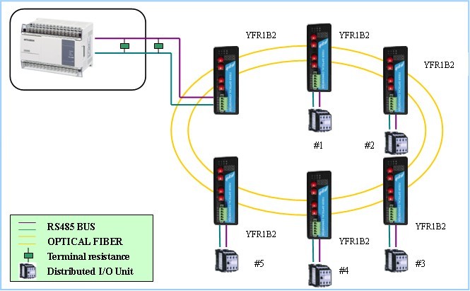
With the development of communication technologies, the disadvantages of slow RS-232 transmission speed, short transmission distance, undefined standard connectors, and poor anti-interference performance are gradually exposed. Therefore, in 1977, the Electronic Industries Association (S1A) in RS Based on the 232, an improved standard RS-499 was proposed and became an American standard in 1980. In addition to being compatible with RS-232, this standard also improves the data transmission rate and increases the transmission distance and other technical parameters. In the following period of time, RS-422, RS-423, and RS-485 standard interfaces were derived from the RS-499. RS-485, also known as EIA-485, was proposed by American EJA in 1983 on the basis of RS-422. Due to its simple wiring, stable and reliable, it is widely used in smart meters, video surveillance, and access control intercom. , building alarm, smart home and other fields. In fact, RS-485 is a variant of RS-422. The two interfaces are different in connection. RS-422 uses two pairs of balanced differential signal lines, so that RS-422 can achieve full-duplex data transmission, and RS-485 With a pair of balanced differential signal lines, only half-duplex data transmission can be completed. RS-232-like, RS-485 also uses negative logic signals, +2 to +6v means 0, -6 to -2V means l, and its receiver minimum sensitivity can reach 200mV, and the communication distance can reach up to 1200m ( By adding 485 repeaters, the communication distance can be extended to 6000m), and the communication rate can be up to lOMbit/s. In a system using RS-485 communication interfaces, one transmission driver can drive up to 32 load devices. The design of the interface device can drive up to 128 load devices and has been used in smart homes. Because the RS-485 bus supports the point-to-multipoint communication mode, and there is no data conflict detection and resolution mechanism, data collision problems are resolved by the host computer. The host computer controls the entire system in a omni-directional manner, avoiding data conflict. In general, since the host must be controlled to avoid data collisions, RS-485-based communication can only support one master-slave communication, and the host needs to be able to recognize multiple slave devices. The device must have a unique address code in the 485 network. The 485 communication host controls the related actions of the 485 communication slave by calling the 485 communication slave address code, which plays a significant role in the smart home system. The RS-485 bus wiring specification stipulates that it must be a bus topology, that is, hand-in-hand daisy-chain wiring, but in the actual construction of the smart home site, the distribution of on-site RS-485 equipment will not always be distributed in a linear manner. It may be scattered in different locations or distributed in a grid, or it may be in a tree distribution. In this case, bus topology wiring is not only a waste of wire, the topology is more complex, and may easily cause RS. The communication quality of the -485 bus system is not stable. Generally, it is necessary to arrange a star topology or a tree topology with some corresponding devices, which is convenient for on-site wiring construction and post-site maintenance work. High Current Terminal Blocks,Panel Terminal Block,Feed Through Terminal Block,Heavy Power Terminal Block Sichuan Xinlian electronic science and technology Company , https://www.sztmlch.com
