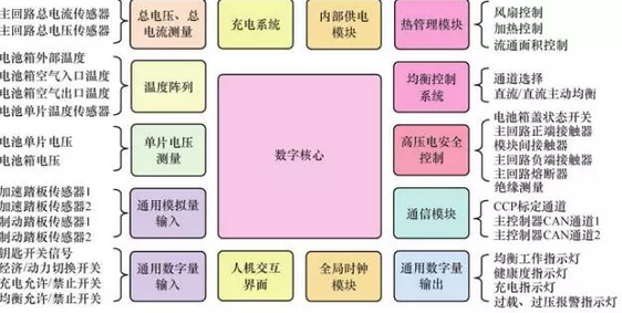
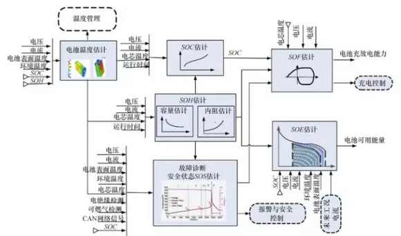
Combining the research situation of electric vehicles in various countries, we can find a common phenomenon that the battery is the most problematic part in the whole electric vehicle research. In the process of battery production, the battery must be subjected to a detection process, that is, the battery needs to be charged and discharged multiple times in the battery production process to complete the production of the entire battery. This article refers to the address: http:// Therefore, the performance of the chemical control system directly affects the technical state and service life of the lithium battery, and determines the degree of pollution to the power grid during discharge. In order to meet the actual operation requirements of electric vehicles, battery management systems have made important efforts in terms of functions, reliability, practicality, and safety. Battery Management System Introduction: Battery Management System (BMS), electric vehicle battery management system (BMS) is an important link between vehicle power battery and electric vehicle. Its main functions include: real-time monitoring of battery physical parameters; battery state estimation; online diagnosis and early warning. ; charge, discharge and precharge control; balance management and thermal management. Battery Management System Applications: The main task of the Battery Management System (BMS) is to ensure the design performance of the battery system: 1) Safety to protect battery cells or battery packs from damage and prevent safety accidents; 2) Durability, the battery works in a reliable safe area, extending the life of the battery; 3) Power, to maintain the battery work in the state of meeting the vehicle requirements. The basic concept of power battery: (1) Battery capacity The pool capacity is an important performance parameter of the battery, which indicates the amount of electricity discharged by the battery under certain conditions of discharge rate, temperature, and termination voltage. The battery capacity is indicated by C, and the unit is expressed in ampere-hour (Ah) and milliampere-hour (mAh). (2) Charging rate and discharge rate This concept is expressed by the ratio of the rated capacity of the battery to the charging time (discharge time), and the charging and discharging speeds of different batteries can be compared. (3) Overcharge of the battery Overcharging of the battery is excessive charging of the battery, and overcharging will cause some damage to the battery. When approaching the end of charging, that is, when the battery is almost full, the battery can only be charged at a low rate with a small current. Because only the polarization caused by small current charging is lighter, less gas is accumulated inside the battery, and the time for cooling the battery is sufficient. (4) Charge termination voltage / discharge termination voltage When the battery is fully charged, it means that the active material on the battery plate has reached saturation state, so even if the battery is continuously charged at this time, the voltage of the battery will never rise again. At this time, the voltage of the battery is called the charge termination voltage. Similarly, the discharge termination voltage is the lowest voltage that can be reached during discharge. (5) Internal resistance of the battery The resistance measured at both ends of the battery is called the internal resistance of the battery. (6) Battery life cycle and aging The battery's entire life cycle goes through three phases: at the beginning of the use phase, the capacity will increase by 5% to 10%; in the next phase, the capacity will remain unchanged; in the final phase, the battery capacity will begin to decrease slowly. This stage of capacity reduction is the aging phase of the battery. In general, when the battery capacity drops to 80% of the rated capacity, the battery life is considered to be over. Figure 1 Basic framework of vehicle BMS software and hardware The main components and functions of the battery management system: (1) Battery terminal module (mainly for data acquisition, such as: voltage parameters, current parameters, temperature, communication signals, etc.); (2) Intermediate control module (mainly communicating with the vehicle system, controlling the charger, etc.); (3) Display module (mainly for data presentation and human-computer interaction). In order to meet the relevant standards or specifications, the following components of the BMS are to be completed: (1) Battery parameter detection. Including total voltage, total current, single cell voltage detection (to prevent overcharging, overdischarging and even reverse polarity), temperature detection (preferably each string of batteries, critical cable connectors, etc.), smoke detection (monitoring electrolysis) Liquid leakage), insulation detection (monitoring leakage), collision detection, etc. (2) Battery status estimation. Including state of charge (SOC) or depth of discharge (DOD), state of health (SOH), functional state (SOF), energy state (SOE), fault and safety state (SOS); (3) Online fault diagnosis. Including fault detection, fault type judgment, fault location, fault information output, etc. Fault detection refers to the diagnosis of fault types and early warning through the collected sensor signals. Battery failure refers to sensor failures of various subsystems such as battery packs, high-voltage electrical circuits, and thermal management, actuator failures (such as contactors, fans, pumps, heaters, etc.), as well as network failures, various controller hardware and software failures. Wait. The fault of the battery pack itself refers to overvoltage (overcharge), undervoltage (overdischarge), overcurrent, ultrahigh temperature, internal short circuit fault, loose joint, electrolyte leakage, and insulation reduction; (4) Battery safety control and alarm. Including thermal system control, high voltage electrical safety control. After the BMS diagnoses the fault, the vehicle controller is notified through the network, and the vehicle controller is required to perform effective processing (the BMS can also cut off the main loop power when a certain threshold is exceeded) to prevent high temperature, low temperature, overcharge, over discharge, and over Flow, leakage, etc. damage to the battery and the human body; (5) Charge control. BMS has a charging management module, which can control the charger to safely charge the battery according to the characteristics of the battery, the temperature and the power level of the charger; (6) Battery equalization. The presence of inconsistencies causes the capacity of the battery pack to be less than the capacity of the smallest monomer in the group. Battery equalization is based on the information of the single battery, using active or passive, dissipative or non-dissipative equalization methods, as much as possible to make the battery pack capacity close to the minimum monomer capacity; (7) Thermal management. According to the temperature distribution information and charge and discharge requirements in the battery pack, the intensity of active heating/heat dissipation is determined, so that the battery works as much as possible at the most suitable temperature, and the performance of the battery is fully utilized; (8) Network communication. BMS needs to communicate with network nodes such as vehicle controllers. At the same time, BMS is inconvenient to disassemble on the vehicle. It needs to be online calibration, monitoring, upgrade and maintenance without removing the shell. The general vehicle network adopts CAN; (9) Information storage. Used to store key data such as SOC, SOH, SOF, SOE, cumulative charge and discharge Ah number, fault code and consistency; (10) Electromagnetic compatibility. Due to the harsh environment of the electric vehicle, the BMS is required to have good anti-electromagnetic interference capability, and the BMS is required to have a small external radiation. Figure 2 Battery Management System Algorithm Framework summary In summary, the mature battery management system should conduct safety monitoring and effective management of the battery pack, improve the battery use efficiency, increase the driving range, extend the battery life, and reduce the operating cost. Battery management systems have made great strides in the development of electric vehicles.
Incremental encoders provide speed, direction and relative position feedback by generating a stream of binary pulses proportional to the rotation of a motor or driven shaft. Lander offers both optical and magnetic incremental encoders in 4 mounting options: shafted with coupling, hollow-shaft, hub-shaft or bearingless. Single channel incremental encoders can measure speed which dual channel or quadrature encoders (AB) can interpret direction based on the phase relationship between the 2 channels. Indexed quadrature encoders (ABZ) are also available for homing location are startup.
Incremental Encoder,6Mm Solid Shaft Encoder,Hollow Rotary Encoder,Elevator Door Encoder Jilin Lander Intelligent Technology Co., Ltd , https://www.landermotor.com
