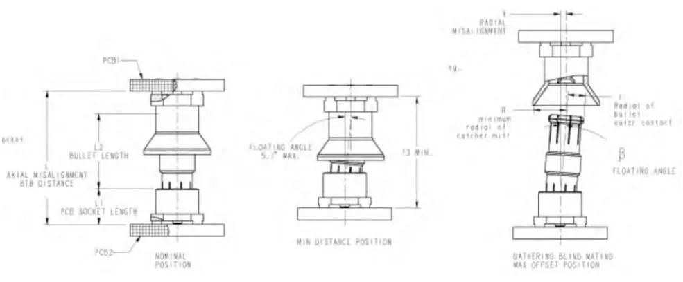
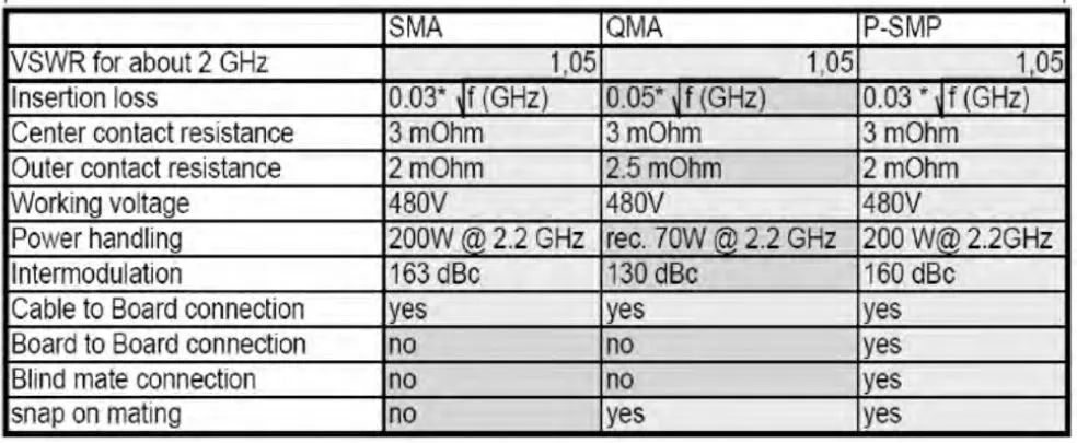
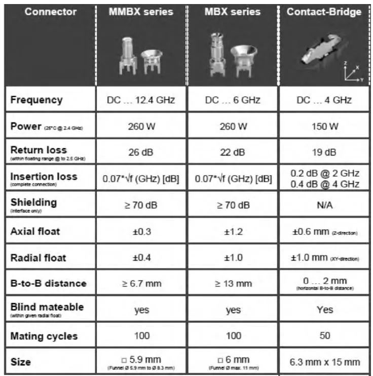
1 The positional relationship between printed boards in communication equipment and the traditional interconnection form The transmission of the system's radio frequency signals across the boards is realized by the erection of radio frequency cable assemblies. Its advantages are: the interconnection is relatively flexible, and the selection range is large; the disadvantages are: high cost, large transmission distance, high space requirements, and complicated installation. As wireless communication applications require increasingly compact equipment, the trend of equipment miniaturization and weight reduction is becoming more and more obvious. The continuous reduction of equipment size requires that the integration of all devices in the equipment becomes higher and higher, and the size of the equipment becomes higher and higher. Coming smaller, this also includes radio frequency coaxial connectors and their cable assemblies that are widely used in and interconnection between radio frequency modules. For example, the RRH (remote radio head), which is widely used in distributed base station systems, must be designed to be very compact in order to be easily, conveniently and reliably installed on the top of towers and in dense urban environments. To try to control its size, this requires that the coaxial interconnection system that carries its radio frequency signal transmission must also be more compact and compact. Traditional and complicated cable assembly connections are being replaced by simple, compact, and reliable "board-to-board" coaxial connector connections that can carry more than 100W of radio frequency signal power. In actual design, the requirements for board-to-board connectors are getting higher and higher, and there are new requirements for the internal RF interconnection. The position between PCBs in the device can be divided into 3 states: horizontal, coplanar, and vertical, as shown in Figure 1: Figure 1 Position between PCBs in wireless communication equipment Figure 2 Types of fit tolerance 2 The design of several types of inter-board connectors 2.1 The tolerance type of the coordination between PCB boards We know that low-frequency connectors have developed a series of corresponding products, and referring to the application of low-frequency connectors, RF connectors also need corresponding connection methods. This is a complete transmission application including power, digital, radio frequency and other different requirements. At the same time, a mixed high-density layout can be realized. However, the requirements for the use environment of the radio frequency signal are much higher than the requirements for the low frequency signal. At the same time, due to the position deviation between the PCB boards and the radio frequency channel and the channel, and the connector itself does not have the flexibility of the cable, under this premise We also need to ensure the basic indicators of insertion loss IL, return loss RL, isolation Isolation and other RF, so we need to optimize the traditional RF connector to overcome these difficulties. The challenges in mechanical structure design brought about by the continuous shrinking of the connector size are mainly in two aspects: First, compared with the large-size connector, the small-size connector is more difficult to match and align. Second, the small size connector has low mechanical strength and is more likely to be damaged if used improperly. Generally, large-size connectors can withstand greater mechanical force during mating without damage, but small-sized connectors need to be more accurate during mating. The three different types of fit tolerances are shown in Figure 2. (1) The radial tolerance means that there is a deviation between the needle shafts of the two center needles during mating. (2) Angle tolerance means that there is an angular deviation when the two center pins are matched. (3) The axial tolerance means that the needle and the seat are not fully matched. For the RF connector, if there is no special design, this kind of incomplete matching will cause impedance mismatch, which will cause signal reflection and increase of standing wave (VSWR). Another important mechanical index is the blind mating range, which indicates the ability of the connector to tolerate deviations. The blind insertion range angle is at least equal to the working tolerance angle, but generally it is much larger than the working tolerance angle. Obviously, when the connectors are mated, it is necessary to consider avoiding the inability to connect or the damage of the connectors due to the hard collision of the two connectors. Allowing a certain degree of tolerance fit will avoid this problem. In addition, allowing tolerance fit also makes blind insertion possible under non-visual conditions. Many blind mating solutions have adopted a "bowl-shaped" design to import the connection. Blind mating improves the design of the connector from a functional level to a user-friendly level. The design should not only consider the effective signal transmission function of the connector, but also be easy to plug and use. 2.2 The design and mechanical and electrical performance of several types of PCB inter-board connectors (1) The first-generation PCB inter-board connectors are currently being gradually promoted as a board-to-board radio frequency solution, the traditional small radio frequency "board-to-board" coaxial connector, For example, MCX does not allow any tolerance, especially the tolerance of the board-to-board axial distance. In the SMB series, a pair of male and female connectors are matched, and the axial and radial deviations are realized through the elastic change of the slotted parts of the female connector. However, due to the limit of the elastic change of the elastic part, the allowable axial and radial deviation The offset is very small, which makes it possible to place no more than three pairs of connectors on the same circuit board. (2) The second-generation PCB board-to-board connector In order to solve this problem, the second type of board-to-board connector came into being, mainly a three-segment coaxial connector. This solution is still based on the principle of coaxial transmission line. To overcome the positional deviation between PCBs, the different inclination angles of the transfer rods in the middle and the gap of the interface are used. We can call this connector application: a three-stage hard-wired solution. Advantages: compact structure, short transmission distance, high placement density, can realize blind mating, easy disassembly and assembly, high test efficiency, better performance than cables, and is conducive to the modular design of products. Such as MMBX, SMP series, by adding an adapter as an intermediate connector, using a three-piece method, the adapter as an intermediate connector can be slightly rotated relative to the socket fixed on the circuit board, thereby allowing a certain degree of comparison. Large radial offset. The intermediate adapter of MMBX can deflect 4.5 degrees, the achievable radial offset is determined by the actual length of the intermediate adapter (L * sin4.5), and the axial floating amount is +/-0.3mm. It can be seen that this type of connector can only allow a limited tolerance, and the allowable tolerance range is very small, and it still requires precise positioning and cooperation. The first and second generation inter-board connectors are shown in Figure 3: Figure 3 First and second generation inter-board connectors Figure 4 Schematic diagram of the third-generation inter-board connector interconnection (3) Third-generation PCB inter-board connectors With the development of equipment, there are more and more pairs of connectors on the same circuit board, and the requirements for the axial and radial floating amount of the connectors are also getting higher and higher ( The third-generation board-to-board connector interconnection diagram is shown in Figure 4). As a result, a new generation of board-to-board solutions was born: such as PSMP, SMP-MAX, MBX, etc. (as shown in Figure 5). This type of application usually Applied in frequency below 10GHz, the tolerance basically meets the use environment of +/-1mm both in the axial and radial directions. SMP-MAX is a new type of board-to-board connection. The sockets at both ends are tight-fitting and loose-fitting, and the middle adapter has two symmetrical ends. In application, first manually match the intermediate adapter with the tight fitting end, and the tight fitting end is designed with a card slot to ensure a large pullout force after the adapter is matched with it. At the same time, there is a larger bell mouth at the loose fitting end for blind insertion guidance, which is convenient for the operator to smoothly import when closing the upper and lower modules (of course, there are guide posts on the upper and lower modules to help the introduction of the connector and prevent petal grooves. Damage). After mating, the adapter can float freely at the loose end, depending on the actual working distance of the upper and lower modules. Figure 5 SMP-MAX series, PSMP series, MBX series connectors SMP-MAX is a board-to-board solution connector with large tolerance capability. SMP-MAX has a radial deflection angle of 3 degrees and an axial float of +/-1mm, even up to +/-1.2mm. The connection interface adopts a unique impedance matching patent technology, even if the board-to-board axial direction reaches the maximum tolerance, when there is a gap as large as 2mm (0.78") between the connectors, a good impedance matching can still be achieved, thereby ensuring that all electrical appliances meet the standard The maximum axial tolerance has even reached 4 times that of SMP. The radial tolerance also has a good performance, which can reach a maximum inclination of 3° in the entire operating frequency range of DC-6 GHz, and at the same time achieve a VSWR better than 1.2 at 3GHz , The maximum power reaches 165 watts. Table 1 Comparison of PSMP and SMA, QMA connectors Another high-power and large-tolerance three-section connector PSMP is shown in Figure 6: Features: ①The application frequency reaches 10GHz; ②The rated power reaches 200W at 2.2GHz; ③The minimum board spacing is 12.6mm; ④Tolerance: Axial + /- 1mm, radial 4°; ⑤ Right-angle elbow connectors are used in cable assemblies. It can be seen that PSMP combines the advantages of SMA, QMA, and SMP to provide good electrical and mechanical properties and large tolerances, as shown in Table 1. In the typical RRH inter-board connector application, the connection between the power amplifier and the filter adopts a three-section PSMP connector. The power amplifier board connector has a shielding reed. At a frequency of 2GHz, the shielding effectiveness can be greater than 60dB. As shown in Figure 6: Figure 6 Application of PSMP connector in a typical RRH 2.3 The RF interconnection design between the PCB board and the module In the RRH, active wire, the RF interconnection from the PCB to the filter, antenna and other modules can be used in addition to the above-mentioned three-segment connector between the boards, as well as hard It is realized in the form of connection to reduce costs and increase flexibility. As shown in Figure 7: Figure 7 Two patented hard connection designs 2.4 RF interconnection design between coplanar PCB boards In the three-stage application, some connector manufacturers have put forward some ideas: whether the space can be more compact and whether the cost is lower. In response to these ideas, they made some attempts, and found that at the expense of certain radio frequency performance, while the distance between the boards is very small, the reed can be used to transmit radio frequency signals. At the same time, it has a certain tolerance capability, and the cost is more than three-stage. Save 2/3. In the low-cost mode, the same connector can be used to transmit radio frequency, digital, and power. To a certain extent, it can be said that it is a universal connector. H Company's bridge connector and its application are shown in Figure 8: Figure 8 H Company's bridge connector and its application The performance comparison between bridge connector and general board-to-board three-section connector is shown in Table 2. Table 2 Performance comparison between bridge connector and board-to-board connector Reed connector application performance requirements: ◆Electrical (electrical performance)·Frequency Range: DC-4 GHz·Return Loss: 20 dB Max·Power: 80 W at 2 GHz (125C Max Ground Plane)·30 W at 4 GHz ( 125C Max Ground Plane)·Isolation (for reference):·5 Position: 31.9 dB @ 2 GHz, 26.2 dB @ 4 GHz·7 Position: 47.8 dB @ 2 GHz, 41.4 dB @ 4 GHz·8 Position: 116.6 dB @ 2 GHz, 106.2 dB @ 4 GHz·Insertion Loss: 0.25 dB Max @ 2 GHz,·0.6 dB Max @ 4 GHz◆Mechanical Misalignment·x axis: +/- 0.5mm mated float·x axis: +/ -0.8 mm gathering ·Y axis: +/- 0.5 mm mated float·z axis: +/- 0.5 mm mated float◆Environment·Max Ambient Temperature: 55°C·Max Ground Temperature: 125°CA Interconnecting the reed structure The connector has made simulations of return loss, isolation, and insertion loss, and made insulation withstand voltage, bonding force, release force, center conductor retention force, pin pull force, plug cycle, vibration, contact resistance, and insulation for single-channel samples. The actual test of various performances such as resistance, voltage standing wave ratio VSWR, characteristic impedance, insertion loss, etc., draws the test conclusion: the product design basically meets the design requirements, and there is room for further optimization of performance. The product has practical significance and can be coplanar on the PCB. And use in the case of parallel plates below 10mm. The stability of the product needs to be verified in subsequent small batches. The experimental samples are shown in Figure 9: Figure 9 A company's new reed structure connector and single-channel and multi-channel experimental samples 3 Conclusion With the widespread deployment of 4G base stations in recent years, the application of small active antennas, small base stations and other equipment, the market requires wireless base station modules such as RRHs to be smaller and smaller in size and more compact in structure, so the application performance is reliable. Small size, large tolerance, and cost-effective inter-board connectors have become the consensus of R&D engineers of various communication equipment manufacturers. According to the specific design requirements of the device, the layout of the PCB board, and the transmission requirements of the radio frequency signal, choosing the appropriate parallel board-to-board connector, the bridge connector between the common boards, etc., is very helpful to the development of wireless devices. Big. In the design of RRH, active antenna, small base station, etc., you can choose according to the following methods: (1) The product is small in size, the PCB board spacing is small, and the tolerance requirements are not high. You can choose MMBX series and similar connectors, which are the smallest The board spacing is 6.7mm. (2) The product volume is large, the PCB board spacing is greater than about 13mm, and the tolerance requirements are higher. PSMP, SMP-MAX, MBX and other series connectors can be selected. (3) For the common panel, bridge connectors, new reed connectors, etc. can be used, which can transmit radio frequency, power, and digital signals at the same time. (4) For the RF connection between the PCB and the filter, antenna and other modules, in addition to the above 1, 2 connectors, hard connections can also be selected according to the actual design to reduce costs and improve flexibility. Our communication equipment R&D engineers can also discuss with the connector suppliers, and cooperate with the connector suppliers to develop new flexible products according to different needs to meet different market needs.
Gaming Headphones is a headset suitable for playing games. For game users, a game headset with excellent performance can allow players to experience the immersive feeling in the game. For competitive game players, the game headset can also assist game players and enhance combat effectiveness.
Gaming Headphones,Gaming Headset,Rgb Gaming Headphones,Gaming Bluetooth Earphones Henan Yijiao Trading Co., Ltd , https://www.yjusbcable.com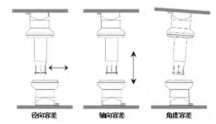
In the case of headphone use, we found that game use would be a large part of the demand, especially the need to use a pure headset to get better listening effect when both music and games are in use.
Compared with music headphones, Wired Game Headphones pay more attention to sound field and positioning sense (for example, shooting and shootout games need positioning), and the amount and intensity of low frequency are aggravated, so as to meet the user's experience of game sound effects. Music headphones, in essence, pay more attention to sound quality. The effect in the right range is super good, with pure sound quality and penetrating sound.
Among the many headsets, Wireless Gaming Headphone have the advantage of sensitivity. The relatively closed listening environment is also more conducive to game players to feel the details of the sound and improve their judgment of the sound. Therefore, compared with traditional headsets, gaming headsets have more advantages in positioning ability, can better express the sense of direction of sound, and are more suitable for 3D games to express sound clearly. In addition, player-oriented game headsets are often enhanced with low-frequency volume sensing to facilitate the game's plot and make it easier for players to immerse themselves in the game.
