The MCM is used to control the LCM module in a very simple way. The LCM module can be viewed as two sets of registers, one for the instruction register IR and one for the data register DR, which is controlled by the RS pin. All access to the instruction register or data register requires checking the busy flag BF inside the LCM. This flag is used to inform the LCM that it is working internally and does not allow any control commands to be received. The check of this bit can make RS=0, and it can be judged by reading D7. When D7 is 0, it can write to the instruction or data register. There are 11 groups of LCM control commands, which are described below. Clear screen The format of the clear screen command is as follows: The instruction code is 01H, and the DDRAM data is all filled in the "blank" ASCII code 20H. Executing this command will clear the contents of the display and the cursor will move to the upper left corner. 2. Cursor homing The cursor homing instruction format is as follows: The instruction code is 02H, the address counter AC is cleared to 0, the DDRAM data is unchanged, and the cursor moves to the upper left corner. × indicates that it can be 0 or 1. 3. Input mode setting The input mode setting command format is as follows: This command is used to set the way the cursor and characters move. The details are shown in the table below. 4. Display switch control The display switch control command format is as follows: The instruction code is 08H to 0FH. This command controls the opening and closing of characters, cursors and flickers. There are three status bits D, C, and B. These three status bits control the display state of characters, cursors, and flickers. D is the character display status bit. When D=1, it is on display; when D=0, it is off display. Note that the off display only shows that the characters do not appear, and the DDRAM content does not change. This is different from the clear screen command. C is the cursor display status bit. When C=1, it is displayed as a cursor; when C=0, the cursor disappears. The cursor is in the form of a bottom line (5 x 1 dot matrix), and the position of the cursor is determined by the address pointer counter AC and moves as it changes. When the AC value is outside the display range of the character, the cursor will disappear. B is the cursor blinking status bit. When B=1, the cursor blinks; when B=0, the cursor does not flash. 5. Cursor, character displacement The format of the cursor and character shift instructions is as follows: Executing this command will produce a character or cursor scrolling one character bit to the left or right. If the instruction is executed at regular intervals, a smooth scroll of characters or cursors will result. The details are shown in the table below. 6. Function settings The function setting command format is as follows: This command is used to set the working mode of the controller. There are three parameters DL, N and F. Their functions are: The DL is used to set the interface form of the controller and the computer. The interface form is embodied in the data bus length. DL=1 sets the data bus to 8-bit length, that is, D7~D0 is valid; DL=0 sets the data bus to 4-bit length, that is, D7~D4 are valid. In this mode, the 8-bit instruction code and data will be transmitted twice in the order of the first 4 bits and the lower 4 bits. N is used to set the number of character lines displayed. N=0 is a line of characters; N=1 is a line of two lines of characters. F is used to set the font for displaying characters. F=0 is a 5×7 dot matrix character; F=1 is a 5×10 dot matrix character. 7. CGRAM address setting The format of the CGRAM address setting instruction is as follows: This instruction writes the 6-bit CGRAM address into the address pointer counter AC. Subsequently, the operation of the data by the microcontroller is a read/write operation to the CGRAM. 8. DDRAM address setting The format of the DDRAM address setting instruction is as follows: This instruction writes the 7-bit DDRAM address into the address pointer counter AC. Subsequently, the operation of the data by the microcontroller is a read/write operation to the DDRAM. 9. Read BF and AC values The format of reading the BF and AC commands is as follows: The LCD's busy flag BF is used to indicate the current working condition of the LCD. When BF=1, it means that the processing of internal data is being performed, and the instruction or data sent by the MCU is not accepted; when BF=0, it means that it is ready to receive the command or data. When the program reads the contents of this data, D7 is the busy flag, and the value of D6~D0 indicates the address in CGRAM or DDRAM. As for which address to point to, it is determined according to the last written address setting instruction. 10. Write data to CGRAM or DDRAM The instruction format for writing data to CGRAM or DDRAM is as follows: Set the CGRAM or DDRAM address first, and then write the data to D7~D0 to make the LCD display the glyph. User-created graphics can also be saved to CGRAM. 11. Read data from CGRAM or DDRAM The format of the instruction to read data from CGRAM or DDRAM is as follows: Set the CGRAM or DDRAM address first, then read the data Transfer from: Chang Xue Electronic Network SMD/SMT Inductor(Coils)
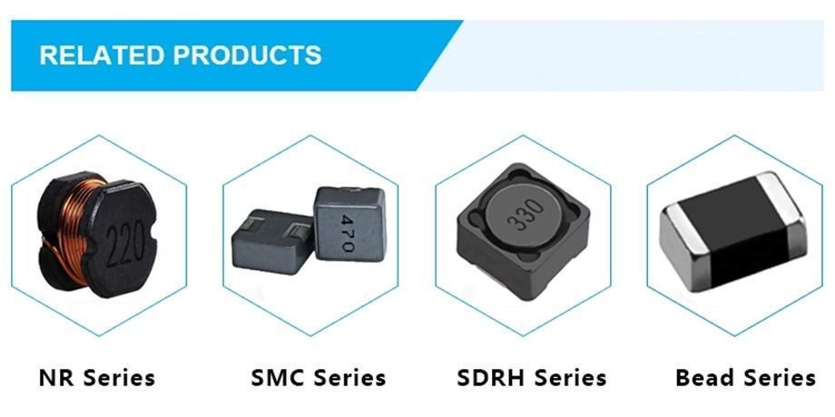
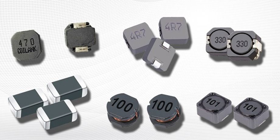
An SMD inductor is a surface mount device inductor. It is a model of inductor that has no wire leads on its ends. This type of inductor is mounted directly to the surface of a circuit board via tining or soldering. They are positive reactance devices, available in many sizes and form factors optimized for particular applications. They are used in circuits that require filtering, power supplies, and many other functions. Inductance is associated with any PCB trace, via and ground plane and is usually considered a parasitic effect in all passive components and integrated circuits with wire bonds.ve components and integrated circuits with wire bonds.
Features:
FAQ
1-MOQ?
We will work hard to fit your MOQ .Small purchase quantity is ok.
2-Payment term?
T/T, Western Union, Paypal, Credit Card
3-Delivery port?
Shenzhen, Guangzhou, Zhongshan, Hongkong.
4-Shipping date?
About 7 days when we check the payment.
5-Do you produce the core and bobbin by yourself .
Yes.we have 2 head company,1 subsidiary company.one is bobbin factory,one is core factory,last one is transformer factory.
6-Where is your factory?
In ShaanxI
Smd Inductor,Smd Power Inductor,Smt Power Inductor,Copper Wire Smd Inductor Shaanxi Magason-tech Electronics Co.,Ltd , https://www.magason-tech.com


â–ªIntegrally molded Power Inductor using a metallic magnetic material.Magnetic shield type and low noise
â–ªIt achieve large current,low Rdc,and compactness
â–ªGood performance in high-temperature environments with good DC superimposition characteristics
â–ªNo Halogen,RoHS compliant
Application:
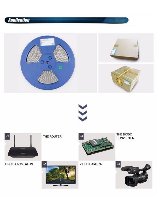
Power supply around the PC,servers,communication devices,automotive electronics,compact power supply modules,others.
