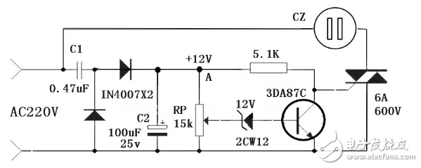
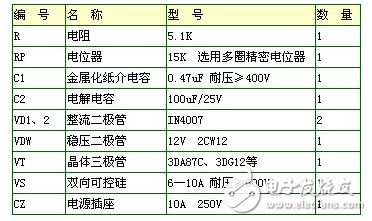
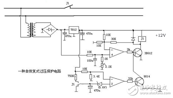
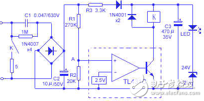
This is a 12V/5A regulated power supply with overvoltage protection. The voltage regulator is composed of a 7805 three-terminal regulator plus a diffuser transistor. The potential of the regulation terminal is boosted by a Zener diode and an LED. high. Overvoltage protection uses a thyristor short-circuit power supply to force the fuse to blow quickly to protect the rear-stage circuit. The circuit diagram is as follows: The normal output voltage of the regulated power supply is 12.2V. When the abnormality of the voltage regulator circuit causes the output voltage to rise to more than 15V, the Zener diode VD2 reverses the turn-on conduction, and the unidirectional thyristor VS control electrode is triggered and turned on. Forcing the 5A fuse FU to blow quickly to protect the rear stage circuit. When the grid voltage suddenly rises for some reason, the operating refrigerators, washing machines, televisions, stereos, computers and other household appliances will be damaged to varying degrees. In severe cases, fires will occur, resulting in a large economy. loss. This paper introduces a simple over-voltage protection device. Once the voltage exceeds the allowable range, it can be automatically powered off. The voltage can be restored to normal and automatically turned on, which protects the home appliance. working principle The working principle of the device is shown in Figure 1. The capacitor C1 is stepped down by the 220V AC mains, and is rectified by the diodes VD1 and VD2, and the capacitor C2 is used as a filter to obtain a DC voltage of about 12V. When the grid voltage is normal, the Zener diode VDW cannot be turned on and turned on. At this time, the triode VT is in the off state, the bidirectional thyristor VS is turned on by the voltage triggering surface, and the home appliance inserted in the socket XS works normally. If the grid voltage suddenly rises, exceeding 250V, the voltage at the midpoint of the RP causes the Zener diode VDW to break through. After the Zener diode is turned on, the transistor VT is turned on. After the VT is turned on, the set is set. The electrode-emitter voltage drop is small enough to trigger VS, which in turn causes the two-way thyristor VS to be turned off. Therefore, the home appliance in the socket XS is powered off and stops working, thus protecting the object. Once the grid voltage drops, VT is turned off again, the collector potential of VT rises, and VS is turned on again, and the home appliance continues to work. The debugging of the device is very simple. When the grid voltage is 220V, adjust the RP so that the VDW does not break down. When the voltage rises to 250V, the VT saturation can be turned on. When using the voltage regulator to simulate the change of the mains. more convenient. Self-recovering DC 12V overvoltage protection circuit In the power-deficient area, the power supply voltage is very unstable. At the peak, it is only 170V up and down, and in the middle of the night it will exceed 250V. In order to protect the increasing number of household appliances, it is necessary to configure an overvoltage protector. I made the overvoltage protector, because of the precision voltage regulator integrated circuit TL431C, the voltage setting is accurate and reliable; the capacitor is used to store the electric energy to drive the relay, so the static power consumption is low, only 0.1W; the short-circuit power supply protection is used at home. electrical appliances can be effectively protected, with ease of use. The specific circuit is shown in the figure, using capacitor step-down and simple regulated power supply circuit. When the supply voltage is normal, the TL431C control voltage is less than 2.5V, the TL431C circuit is not conducting, and the relay contacts are not closed. When the mains voltage reaches 250V, the current after rectification and filtering reaches 3.3mA, and the voltage drop on R3, diode and Zener (including the arc tube) is 11V and 26V respectively. The voltage of 37V is divided by R1 and R2, and the voltage at point A is 2.55V. The TL431C circuit is turned on, the relay K is pulled in, and the mains is short-circuited, so that the power supply current device trips or the fuse is blown, which protects the household appliances. Here, a small resistance resistor is connected in series in the contact loop to prevent excessive short-circuit current from burning out the contacts. Since the capacitor C3 has a large capacity, a large amount of charge is stored and applied to the relay coil, so that the relay contact can maintain a 0.2 second pull-in time, which is enough to cause the overcurrent to trip or the fuse to blow. The current limiting capacitor C1 selects a 0.47μF/630V polystyrene capacitor. To prevent incorrect connection to the 380 line voltage, C1 should have the necessary withstand voltage. Relays should be based on the size of the power, using small or ultra-small large and medium power contact relays, such as JQX13-F/024-1Z or JZC-22F/024-1Z. The 5Ω current limiting resistor is made of 5W cement resistor, and other components are selected according to the figure. The whole circuit can be installed in a small plastic box, the power pin is fixed at the bottom of the plastic box, and the light emitting diode is exposed on the plastic box surface.
1.5"~2" speaker (40~50mm)
1)1.5" speaker 40mm speaker
FAQ
Q1. What is the MOQ? 1.5" Speaker 40Mm Speaker,1.75" Speaker 44Mm Speaker,1.8" Speaker 45Mm Speaker,1.9" Speaker 48Mm Speaker Shenzhen Xuanda Electronics Co., Ltd. , https://www.xdecspeaker.com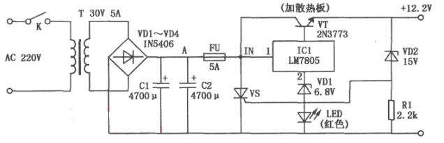
2)1.75" speaker 44mm speaker
3)1.8" speaker 45mm speaker
4)1.9" speaker 48mm speaker
5)2" speaker 50mm speaker


XDEC: 2000pcs for one model.
Q2. What is the delivery lead time?
XDEC: 15 days for normal orders, 10 days for urgent orders.
Q3. What are the payment methods?
XDEC: T/T, PayPal, Western Union, Money Gram.
Q4. Can you offer samples for testing?
XDEC: Yes, we offer free samples.
Q5. How soon can you send samples?
XDEC: We can send samples in 3-5 days.
12v overvoltage protection simple circuit diagram Daquan (four analog circuit design schematics detailed)
12v overvoltage protection simple circuit diagram (1)