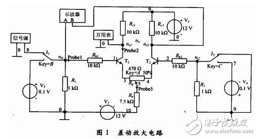
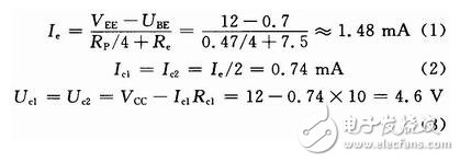
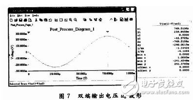
In an automatic control system, it is often necessary to convert some slowly changing physical quantities (such as changes in temperature and speed) into corresponding electrical signals and amplify them by a DC amplifier. Although the direct coupling amplifier circuit can amplify the AC and DC signals, the fluctuation of the power supply voltage, the transistor parameters change with temperature and other factors will cause the circuit to have a “zero driftâ€. The differential amplifying circuit is a DC amplifier that effectively suppresses the "zero drift" by utilizing the symmetry of the circuit structure parameters, and has the amplification capability for the differential mode signal and the suppression of the common mode signal. A typical differential amplifier circuit consists of two single-tube common emitter circuits with identical parameters. MulTIsim 10 is a powerful electronic circuit simulation design software from National Instruments (NI). It has a wealth of new components and virtual instruments, powerful Spice simulation, data visualization and analysis and testing functions. It can be used for analog, digital, and Automatic control, RF, MCU and other circuits for schematic design, simulation analysis and functional testing. MulTIs-im 10 provides a powerful schematic capture and interactive simulation platform. The design and debugging of the circuit, the calling of components and test instruments, the use of various analysis methods are intuitive and convenient, the test parameters are accurate and reliable, and it is widely used. EDA system. This paper takes a typical differential amplifier circuit as an example, and mainly discusses the application of various analysis methods of MulTIsim 10 in electronic circuit simulation design. A typical differential amplifier circuit as shown in Fig. 1 is built in MulTIsim 10. T1 and T2 are both NPN transistors (2N2222A), and the current amplification factor β is set to 80. Toggle switches J1, J2 can optionally add DC or AC signals to the input of the differential amplifier circuit. The digital multimeter is used to measure the DC output voltage. The oscilloscope is used to observe the AC input/output voltage waveform. The measurement probe is used to display the voltage and current of the branch to be tested in real time. In the actual circuit, T1 and T2 should use differential pair tube, and the quiescent current ICQ of the transistor should not exceed 1 mA. ICQ can select the emitter resistance Re shared by the two tubes, and Re does not affect the differential mode voltage amplification factor, and has strong negative feedback effect only on the common mode signal, so it can effectively suppress the “zero point drift†and stabilize the static working point. . Since the parameters of the two amplifiers are not completely identical, the circuit is zeroed by the potentiometer Rp. The base resistors Rb1, Rb2 should be selected according to the requirements of the differential mode input resistance. When collecting the collector resistors Rc1 and Rc2, the static working point should be close to the midpoint of the load line. According to the difference between the input and output terminals, the differential amplifier circuit has the following four different connections: double-ended input double-ended output, double-ended input single-ended output, single-ended input double-ended output, single-ended input Single-ended output. In Figure 1, the differential amplifier circuit is static, the signal is not applied to the input terminal, and the base potential of T1 and T2 is approximately zero. Therefore, the potential across the potentiometer Rp is -UBE (about -0.7 V for the silicon tube), such as the potential. The sliding end of the Rp is at the midpoint and the static working point is calculated as: The DC working point analysis method in Multisim 10 is the basis for further analysis of the circuit. It is mainly used to calculate the static working point of the circuit. At this time, the AC power supply in the circuit will be set to zero, the inductor is short-circuited, and the capacitor is open. For static working point analysis, the node number of the circuit needs to be displayed on the circuit diagram (see Figure 1), and the node number to be analyzed needs to be selected. Execute the Simulate/Analyses/DC Operating Point analysis command in turn to set 1, 2, u01, u02, Iprobe2, and Iprobe3 as output nodes (variables) in Figure 1, and obtain the static working point analysis result shown in Figure 2. :Ie=1.48 mA, Ic1=Ic2=0.732 mA, Uc1=Uc2=4.68 V, and the measured parameters are basically consistent with the analysis results of equations (1) to (3). We specialize in cable assembly overmolding. Our customized molded cables are built precisly following customers' spec.Experienced proposal can be offered to customers for evaluation by considering stable quality and competitive price.
Custom cable overmoldings improve the quality, look and functionality of many electrical cables. From battery interconnects and molded plugs to custom molded plugs and many other custom designed assemblies – ETOP is a premier custom cable overmolding supplier to OEMs.
Molded Cables,Stranded Round Molded Cables,Molded Patch Cord Cable,4 Pole Waterproof Molded Cable,Waterproof Connectors ETOP WIREHARNESS LIMITED , https://www.wireharness-assembling.com

