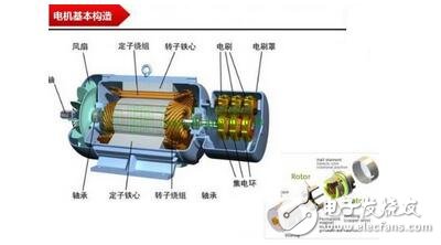
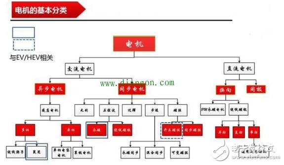
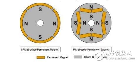
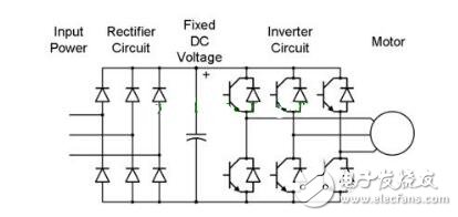
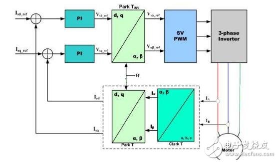
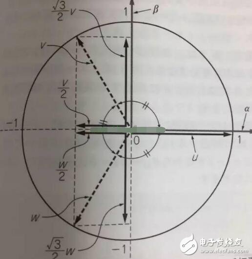
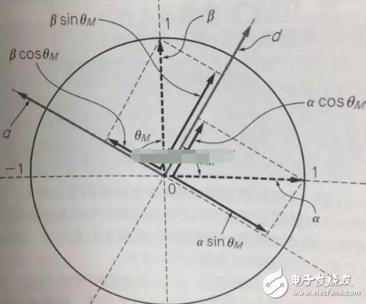
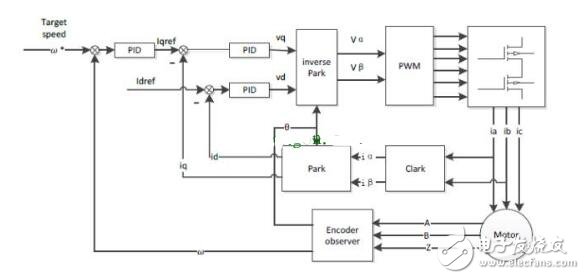
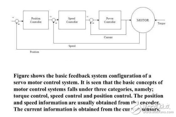
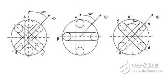
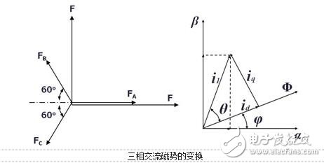
The rotor inside the servo motor is a permanent magnet. The U/V/W three-phase electric motor controlled by the driver forms an electromagnetic field. The rotor rotates under the action of the magnetic field. At the same time, the encoder feedback signal from the motor is supplied to the driver. The driver according to the feedback value and target. The values ​​are compared to adjust the angle at which the rotor rotates. The accuracy of the servo motor is determined by the accuracy of the encoder (number of lines) There are many papers and various articles on the vector control technology of AC motors. However, it is often explained in terms of difficult formulas and coordinates. If there is no solid theoretical basis such as mathematics and control, I believe that it is more difficult to understand. Riccijun tries to use simple and easy-to-understand diagrams and calculations to talk about motor construction, static and rotating coordinate changes, vector control, servo control and other motor drive technologies. Before we talk about control, in order to better understand the control, let us first look at the construction of the motor. The structure of the motor applied in real time is very complicated, but it can be simply understood as follows: the motor is composed of a rotor mounted inside and a stator mounted on the outside (there is also a motor opposite thereto). A permanent magnet is generally placed inside the rotor, and a copper wire is generally wound inside the stator. . Then insert the center axis in the middle to drive the object. After hundreds of years of development, motor technology has formed various classifications as above. The magnets used in motors are rare metals, and the output is mainly distributed in China. In recent years, due to the high price of rare earth materials, the industry is actively studying how to reduce the use of rare earths, maintain performance while reducing product costs, and is an enterprise engineer. Forever subject. Synchronous motors are widely used in practical applications today. The synchronous motor is also loaded with magnets, mainly classified into SPM (surface magnet) and IPM (internal magnet): Due to the simple control, the SPM motor has been used by the industry in the early days. However, since the magnet is mounted on the surface of the rotor, the power that can be utilized is mainly derived from its own surface magnet. IPM motors are widely used this year because they can use the power of magnetism and magnetism around the magnet to generate high-density energy and reduce the amount of rare earths used in construction. Let's get into the topic and talk about the control of the AC motor. The general motor drive inverter is shown above. We can see that the output of the IGBT and the input of the motor are three phases (voltage, current UVW), while the magnet inside the motor has only two poles of S and N. At the same time, the three-phase UVW belongs to the stationary coordinate, and the motor belongs to the rotating coordinate when running. Then we need to control the motor to exchange the three-phase static coordinate with the two-phase rotating coordinate according to our purpose. Let's first look at the structure diagram of the vector control: The three-phase AC value is obtained from the current sampling of AC Motor, converted into two-phase coordinates (αβ) by Clark, and the static αβ coordinates are replaced by the dq coordinates of the rotation by Park transformation to form a feedback value, and the command value of dq is calculated. . Through the calculation result of the PI controller, we can obtain the voltage command value of dq two-phase, and the dq command value of the rotating coordinate is transformed by inverse Park to obtain αβ of the stationary coordinate, and then the three-phase voltage drive command is obtained by inverse Clark conversion. Controls the output of the SVPWM. In addition, the d-axis corresponds to the torque generated by the excitation, and the q-axis corresponds to the torque generated by the permanent magnet. In the control of the SPM motor, we can make the d-axis command value 0. However, in the IPM motor control, both the d-axis and the q-axis are utilized, so the output of the two commands is required in the speed loop. The following is a forward Clark transform and a Park transform to calculate how to coordinate transformation: Clark transform We set the U and α axes to be the same, and assume that k is the vector amplitude ratio coefficient of the three-phase and two-phase. Through the above illustration we can get: α = k{ U - 1/2V - 1/2W} β = k{ sqrt(3)/2V - sqrt(3)/2W } Due to the three-phase balance, we can have: U + V + W = 0 α = U Bring in the above formula to get: k = 2/3 So β = 1/sqrt(3)*(VW) = 1/sqrt(3)*(U+2V) Park transform We assume that there is an angle of θ between the αβ axis and the dq axis, and decompose αβ onto the dq axis, and then use the trigonometric formula to get: d = αcosθ + βsinθ q = -αsinθ + βcosθ The inverse transformation of the rotated coordinates and the stationary coordinates is the same as above, and is omitted here. Above we talked about coordinate transformation and vector control structure. The purpose of vector control is to control the servo while making the current and voltage levels consistent to improve the efficiency of power efficiency and motor torque. Let's take a look at the servo control structure including vector control. The above structure can be simplified as follows: position control loop, speed control loop, vector (current) control loop. The vector control of AC motor is analyzed. In the AC motor control which actually uses the inverter, due to the influence of external disturbance, temperature, high frequency and so on, the motor control algorithm is more and more complicated and the accuracy is higher and higher, but we only need Mastering the most basic methods described above helps to understand other developmental algorithms. 1. Vector control of AC induction servo motor Vector control theory was first proposed in 1971 by the German scholar F.Blachke. In the servo system, the DC servo motor can obtain excellent dynamic and static performance, and the root cause is that only the motor flux Ф and the armature current Ia are controlled, and the two quantities are independent. Further, the electromagnetic torque (Tm = KT Ф Ia) is proportional to the magnetic flux Ф and the armature current Ia, respectively. Therefore, the control is simple and the performance is linear. If the DC motor can be simulated, and the corresponding magnetic field and armature current of the AC motor are obtained and controlled independently, the AC motor has excellent characteristics similar to those of the DC motor. To this end, the three-phase cross-variable (vector) must be converted to the equivalent DC amount (scalar), the equivalent model of the AC motor must be established, and then controlled by the DC motor control method. The three-phase asynchronous AC motor shown below produces a rotating magnetic field Φ with an angular velocity of ω0 in space. If two sets of spaces α and β with a difference of 900 in Fig. b are used instead, and an alternating current with a phase difference of 900 in phase is used to generate a rotating magnetic field Φ with an angular velocity of ω0, it can be considered as a. It is equivalent to the two sets of windings in Figure b. If the two mutually perpendicular windings d and q on the model shown in Figure c are respectively passed with DC currents id and iq, a fixed magnetic field Φ will be generated. If the winding is rotated at an angular velocity ω0, the established magnetic field is also The rotating magnetic field has the same amplitude and speed as in Figure a. Three-phase A, B, C system transformation to two-phase α, β system This transformation is to convert a three-phase AC motor into an equivalent two-phase AC motor. The three-phase stator windings of the three-phase asynchronous motor shown in the above figure a differ from each other by 1200 spatial angles. When the three-phase balanced alternating currents iA, iB, iC are connected, a magnetic field vector Φ is generated on the stator at a synchronous angular velocity ω0. . The function of the three-phase winding can be completely replaced by two stationary α, β windings which are spatially perpendicular to each other, and the alternating-phase currents iα and iβ whose phases are different in time by 900 are used to generate a rotating magnetic field. The amplitude and angular velocity are also Φ and ω0, respectively, then it can be considered that the two sets of windings in the above figures a, b are equivalent. Apply the three-phase/two-phase mathematical transformation formula to convert it into the equivalent AC magnetic field of the two-phase AC winding. The resulting spatial rotating magnetic field coincides with the rotating magnetic field generated by the three-phase A, B, and C windings. Let the axis of the A-phase winding in the three-phase winding coincide with the α-axis, and the magnetic potential is According to the relationship between the magnetic potential and the current, the corresponding current values ​​iα and iβ can be obtained. Three-phase alternating magnetic potential transformation In addition to the transformation of the magnetic potential, the other physical quantities used in the transformation are the same as long as the three-phase balance and the two-phase balance. This converts the three-phase motor into a two-phase motor. Vector rotation transformation After converting a three-phase motor into a two-phase motor, it is also necessary to convert the two-phase AC motor into an equivalent DC motor. If d is the excitation winding, the excitation electric id, q is the armature winding, and the armature current iq is passed, and the magnetic field Φ of a fixed amplitude is generated, and is rotated at the angular velocity ω0 on the stator. This can be seen as a DC motor. The transformation of a two-phase AC motor into a DC motor is essentially a vector-to-scalar conversion, which is a conversion between a stationary Cartesian coordinate system and a rotating Cartesian coordinate system. Here, iα and iβ are converted into id and iq, and the conversion condition is to ensure that the synthetic magnetic field does not change. The composite vector of iα and iβ is i1, and it is projected in the Φ direction and the vertical direction to obtain id and iq. Id and iq rotate in space at an angular velocity ω0. The conversion formula is Cartesian and polar transformation In the vector control, the transformation of the Cartesian coordinate system and the polar coordinate system is also used. Find i1 from id and iq, the formula is The induction motor with vector transformation has the same control characteristics as the DC motor, and the structure is simple and reliable, and the motor capacity is not limited. Compared with the same DC motor, the mechanical inertia is small. The induction motor with vector transformation has the same control characteristics as the DC motor, and the structure is simple and reliable, and the motor capacity is not limited. Compared with the same DC motor, the mechanical inertia is small. 2. Vector control of AC synchronous motor Fundamental In a DC motor, regardless of the position of the rotor, the armature magnetomotive force generated by the rotor current is always at an electrical angle of 90° to the magnetic field generated by the stator pole. Therefore, its torque is in a simple proportional relationship with the armature current. The stator of the AC permanent magnet synchronous motor has a three-phase winding, the rotor is a magnetic pole formed by a permanent magnet, and the rotor position encoder is coaxially connected to detect the relative position of the rotor pole relative to each winding of the stator. This position is associated with a sinusoidal relationship of the rotor angle. The position encoder and the electronic circuit are combined such that the current flowing in the three-phase winding and the rotor position angle are in a sinusoidal relationship, which is different from each other by an electrical angle of 120°. The rotational magnetomotive force of the three-phase current synthesis always has a 90° electrical angle (leading) in the direction of the space with the rotor magnetic field, generating maximum torque. If the relationship between the permanent magnet magnetic field, the armature magnetomotive force and the torque can be established, In the speed regulation process, the control of the current is used to achieve the torque control, which is the purpose of vector control. Shenzhen Chaoran Technology Corp. , https://www.chaoran-remote.com