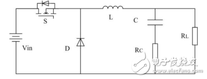
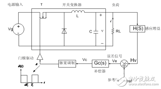
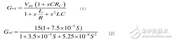
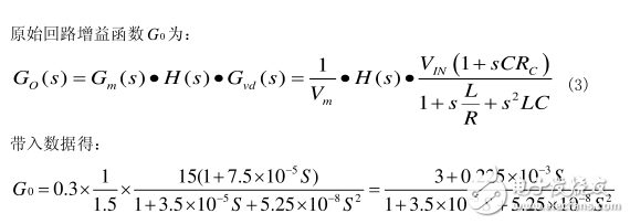
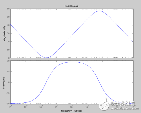
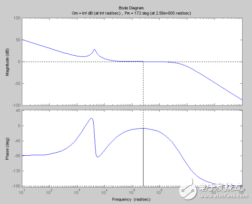
The BUCK circuit is a buck chopper, and the buck converter output voltage average UO is always less than the input voltage Ui. Usually the current in the inductor is continuous, depending on the switching frequency, the filter inductance L and the capacitance C value. The voltage output of the simple BUCK circuit is unstable and will be interfered by the load and the external. When the PID controller is added, the closed-loop control is realized. The PWM modulated wave can be obtained through the sampling link, and then compared with the reference voltage, and the feedback signal is obtained by the PID controller, and compared with the triangular wave, the modulated switching waveform is obtained, which is used as a switching signal, thereby realizing the closed loop PID control system of the BUCK circuit. . The functions that the circuit design can achieve are as follows: Input DC voltage (VIN): 15V Output voltage (VO): 5V Output current (IN): 10A Output voltage ripple peak-to-peak Vpp "50mV Sawtooth amplitude Um=1.5V Sampling network transmission H(s)=0.3 The on-state voltage drop of the BUCK main circuit diode is VD 0.5V, The resistance drop in the inductor is VL=0.1V, the turn-on voltage drop of the switch is VON=0.5V, and the product of the filter capacitor C and the electrolytic capacitor is 75μΩ*F. Parameter Design of Buck Converter PID Control PID control is controlled according to the ratio of deviation P), integral I), differential D), which is the most widely used control system - a control law. By adjusting the proportional, integral and differential parameters, most industrial control systems achieve good closed-loop control performance. The main circuit Bode diagram of lead lag corrector After adding the compensator Bode diagram of the system after adding the compensator
BIOTEPT motor Cost effective and food safe. Stainless steel IEC motors from BIOTEPT excel in power, efficiency and food safety. With the IEC stainless steel motors you benefit from a cost-effective and food-safe drive that is suitable for applications where hygiene plays an important role.
DAYTON, LEESON, MARATHON MOTORS and U.S. MOTORS
IEC Serie – IEC Stainless Steel Motors: main features
Iec Stainless Steel Motor,Waterproof Electric Motor,Waterproof Motor,Water Resistant Motor Ningbo Biote Mechanical Electrical Co.,Ltd , https://www.biotept.com