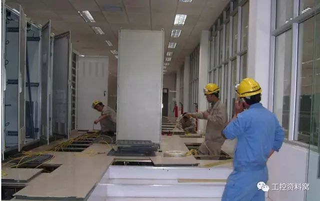
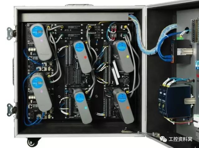
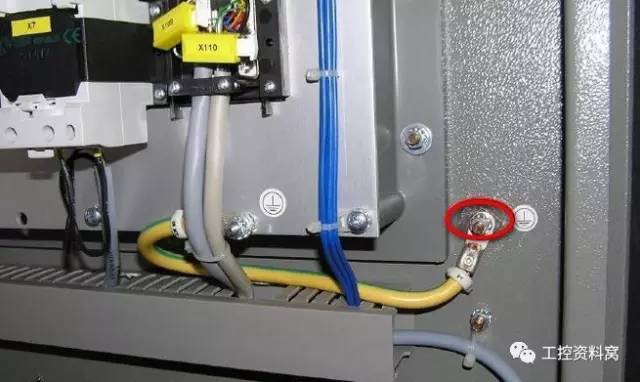
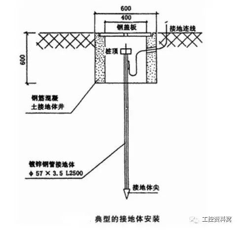
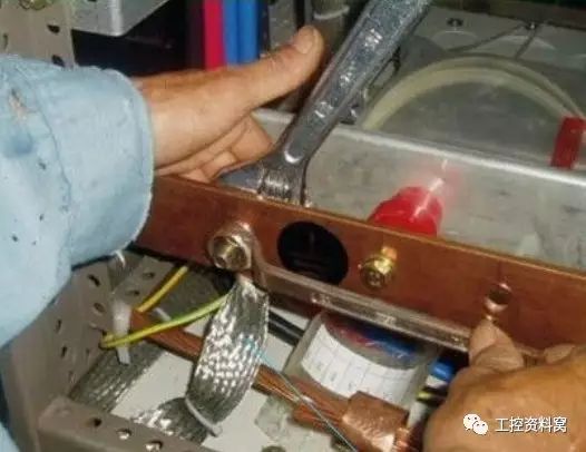
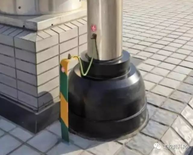
Lead in this issue Some time ago, we pushed an article "[Working ground, protective grounding, protection zero and repeated grounding] dizzy? After reading this article, suddenly! "A text. In this issue today, we talk about the grounding of DCS. DCS reasonable and reliable system grounding is a very important part of the DCS system. In order to ensure the monitoring and control accuracy and safe and reliable operation of the DCS system, it is necessary to carefully consider the system grounding method, grounding requirements, signal shielding, grounding line section selection, and grounding pole arrangement. First, the basic requirements of DCS system grounding The DCS system is grounded to ensure that when a signal entering the DCS system, the power supply, or the DCS system itself has a problem, the effective grounding system can withstand the overload current and can quickly introduce the overload current into the ground. The grounding system provides a shield for the DCS, eliminates electronic noise interference, and provides a common signal reference point (ie, reference zero potential) for the entire control system. When there is a problem with the grounding system (grounding resistance is too large, multi-point grounding, grounding wire disconnection or grounding wire is in contact with high-voltage, high-current equipment, etc.), it may cause electric shock damage and equipment damage. It is understood that some DCS systems often "crash" (or "dead" for unknown reasons), mostly due to poor grounding or problems. Therefore, perfect, reliable and correct grounding is the key to the safe, reliable and good operation of the DCS system. Second, DCS grounding classification In general, DCS control systems require two types of grounding: protective ground and work ground (logically, shielded, etc.). Intrinsically safe areas are also required for systems equipped with safety barriers such as those used in the chemical industry. 2.1 Protected Area (CG, Cabinet Grounding) It is a protective measure taken to prevent static charge accumulation in the device casing and to avoid personal injury. All operator cabinets, field control station cabinets, printers, terminal cabinets, etc. of the DCS system should be connected to the protection ground. The protection ground should be connected to the electrical professional grounding grid of the plant, and the grounding resistance is less than 4Ω. 2.2 logically Also called the machine logic ground, the host power supply ground, is the logic level negative internal common ground of the computer, and is also the power output ground of +5V. Such as the positive and negative 5 volts of the CPU, the negative end of plus or minus 12 volts. Need to access the common grounding pole. 2.3 shielding ground (AG, Analog Grounding) Also called analog ground, it can shield the interference received by the live signal transmission to improve the signal accuracy. The shield of the signal cable in the DCS system should be shielded to ground. The cable shield must be grounded at one end to prevent closed loop interference. The metal é“ of the armored cable shall not be used as a shielded protective ground. It must be grounded with a copper mesh or aluminized shield. Connect to the common grounding pole. 2.4 intrinsically safe The grounding system should be set independently and the grounding resistance should be ≤ 4Ω. The grounding system of the intrinsically safe ground should be kept independent, and the distance from the electrical grounding network of the plant area or the grounding network of other instrumentation systems should be more than 5m. Third, DCS system grounding method 1 Using an electrical grounding grid as a DCS grounding grid, that is, co-located with an electrical grounding grid; 2 Set a separate grounding grid for the DCS system; 3 Set the DCS dedicated grounding grid, and then connect to the electrical grounding grid via the grounding wire. Since the third grounding method has more in common with the second grounding method, in the past, a computer or DCS system used a dedicated grounding grid. However, the shortcomings of this grounding method are: too large floor space, high investment, large consumption of steel for cables and grounding grids, and considerable distance from the factory building (because it is not easy to find a suitable location in the factory), management, maintenance, It is not convenient to measure and find the grounding and grounding wires, and the effect is not good. According to the actual operation, it is difficult and unsafe to set up a dedicated DCS grounding grid. Fourth, the requirements for the common grounding pole (net) 1 When the distribution resistance of the electrical grounding grid of the plant to the ground is ≤ 4Ω, the electrical grounding grid of the plant can be regarded as the common grounding pole (net) of the DCS system. 2 When the grounding resistance of the electrical grounding grid of the plant is large or disordered, the grounding system should be set independently, which is the common grounding pole (net) of the DCS system. 3 The common grounding pole (net) without intrinsically safe ground has a ground-distributed resistance of less than 4 Ω; and an intrinsically safe ground of less than 1 Ω. The line impedance of the grounded mains is less than 0.1Ω. 4 There is no access point for lightning protection within 15 meters around the grounding pole, and there is no access point for the high and low voltage electrical equipment casing of 30KW or more within 8 meters. When the condition cannot be met at the site, the lightning protection ground is connected to the main line of the common ground through the arrester/shock suppressor. The welding ground should not be overlapped with the common grounding pole and its grounding grid. The distance between the two should be more than 10 meters. V. Grounding principle of DCS system 1. Grounding device set by DCS system 1.1 Operation console, printing station, server cabinet: There are protective ground screws. 1.2 Relay cabinet, UPS cabinet, power distribution cabinet: with protective grounding screws. 1.3 DCS I/O cabinet: It has a shielded ground busbar, a grounding screw, and a system ground (+24V ground) suspension. 1.4 Instrument cabinet, hand panel: There is a shielded grounding busbar and a grounding screw. 1.5 Safety barrier cabinet: It is equipped with shielded grounding busbar, intrinsically safe grounding busbar and protective grounding screw. 2. Signal shielding and grounding According to the relevant technical regulations, the shielding layer of the signal cable of the computer or DCS system shall not be floating and must be grounded. The grounding method shall comply with the following regulations: 2.1 When the signal source is floating, the shielding layer should be grounded on the computer side; 2.2 When the signal source is grounded, the shielding layer should be grounded on the signal source side; 2.3 When the amplifier is floating, one end of the shielding layer is connected to the shield cover, and the other end should be connected to the common mode (when the signal source is grounded, the signal ground is connected. When the signal source is floating, it is connected to the site); 2.4 When the shielded cable passes through the junction box to be disconnected or combined, the shield of the cable at both ends should be connected in the junction box. Sixth, DCS system grounding method to reduce soil resistivity 1 Change the soil structure around the grounding body. In the range of 2 to 3 m of soil around the grounding body, a water-absorbable material with good water absorption, such as charcoal, coke cinder or slag, can be added to reduce the soil resistivity to 1/5. ~1/10. 2 Use salt and charcoal to reduce soil resistivity and layer and compact with salt and charcoal. Charcoal and finely mixed into a layer, about 10 ~ 15cm thick, and then spread 2 ~ 3cm of salt, a total of 5 ~ 8 layers. After paving, tap into the grounding body. This method can reduce the resistivity to 1/3 to 1/5 of the original. However, salt will be lost with running water for a long time, and it will be supplemented once more than two years. 3 Use a long-acting chemical resistance reducer. The long-acting chemical drag reducer method can reduce the soil resistivity to 40%. Seven, DCS system grounding materials and requirements 1. Material requirements for grounding body and grounding grid mains The specifications of the steel used for the grounding body and the grounding grid can be selected as shown in the following table. If the grounding resistance does not meet the requirements, copper can also be used. If the grounding body and the grounding grid mains are installed in a corrosive place, anti-corrosion measures such as hot-dip galvanizing and hot-plating should be adopted according to the nature of the corrosion or the cross-section should be appropriately increased. 2. Grounding connection requirements The protective ground and shield ground connection of the DCS system shall be connected to the electrical grounding grid or grounding body of the plant area using copper-cored insulated wires or cables. When the grounding connection distance is long, the DCS system requires a higher grounding resistance or the number of branching lines of the grounding trunk is larger, the wire and cable with a larger cross section in the table should be used. Eight, the site grounding common precautions Field control station The grounding screw is insulated by the rubber between the cabinet body and the base, and the shielding grounding bus is insulated from the base. The site control station must be grounded as required. That is, they are connected to the grounding busbar of the field control station. The power ground of the I/O cabinet and the power ground of the UPS must be connected to the same ground to ensure equipotentiality. 2. Each hardware device The operator station, engineer station, network switch, server host, system display, etc. are grounded by the outer casing or directly connected to the electrical grounding grid. 3.I/O components The 40-terminal of the analog module, that is, the negative terminal of 24 VDC, is connected to the logic bus, logically connected to the shield ground, and then connected to the total ground bus. 4. Shielding ground The protection ground of the on-site control station should be connected to the grounding sub-trunk from the grounding screw below the cabinet. The shielding ground of the on-site control station should be connected from the grounding confluence to the common connecting plate. 5. Grounding resistance test The resistance of the grounding system must be tested to ensure that the grounding meets the requirements of the control system manufacturer. Nine, grounding construction specifications 1 The normal uncharged metal parts of the electric instrument's outer casing, instrument panel, cabinet, box, box and cable trough, protection tube, bracket, base, etc., which may be dangerously damaged due to insulation damage, should be protected and grounded. For local instruments, switches, etc. with a supply voltage not higher than 36V, when there is no special requirement for the design file, the protection grounding may not be performed. 2 In the non-explosive hazardous area, the metal casing of the small-sized low-voltage electrical appliances such as buttons, signal lamps, relays, etc. installed on the metal plate, when the contact with the grounded metal plate and plate is good, the protective grounding may not be performed. 3 The instrument protection grounding system should be connected to the protective grounding network of electrical engineering low-voltage electrical equipment. The connection should be firm and reliable, and should not be connected in series. 4 The grounding resistance of the protective earthing shall be in accordance with the design documents. 5 Cable troughs and cable protection tubes installed on buildings can be grounded repeatedly. 6 The instrument and control system should be grounded. The working grounding includes signal circuit grounding and shielding grounding, as well as the intrinsically safe circuit grounding of special requirements. The grounding system connection method and grounding resistance value should conform to the design documents. 7 The signal loop grounding and shielding grounding of the instrument and control system should share the grounding device. 8 Each instrument loop should have only one signal loop ground point unless an isolators are used to isolate the DC signal loop between the two ground points. 9 The grounding point of the signal loop should be on the side of the display instrument. When the grounded thermocouple and the instrument whose grounding element is grounded are used, it should not be grounded on the side of the display instrument. 10 The shielding layer of the instrument cable should be grounded on the side of the instrument panel of the control room. The shielding layer of the same circuit should have reliable electrical continuity. It should not be floating or repeatedly grounded. It should not be grounded in the display instrument. The shield of the field instrument side cable shall not be exposed outside the protective layer. 11 When there is anti-interference requirement, the spare core wire in the multi-core cable should be grounded at one point. The spare core wire and cable shielding layer of the shielded cable should be grounded on the same side. 12 All kinds of grounding of each circuit in the instrument panel, cabinet and box should be led to the grounding busbar or grounding terminal board by the respective grounding branch, and the grounding trunk should be led out by the grounding busbar or the grounding terminal board, and then the grounding main trunk and grounding Extremely connected. Each grounding branch, busbar or grounding terminal strip shall be insulated from each other at the non-joining point. 13 The connection of the grounding system should be made of copper-cored insulated wire or cable, which is fixed by galvanized bolts. The grounding busbar of the instrument panel, cabinet, box and inner should be made of copper and fixed by insulating bracket. Welding should be used between the grounded mains and the grounding body. 14 The intrinsically safe circuit itself should not be grounded except as specified in the design documentation. When a diode barrier is used, its ground should be connected to the common end of the DC power supply. 15 Anti-static grounding should be in accordance with the design documents and can be carried out simultaneously with equipment, piping and electrical anti-static engineering. 16 The grounding connection shall be made of stranded copper core insulated wires or cables, which shall be connected by galvanized or copper bolts. The grounding busbar shall be made of copper and fixed by insulating brackets. 17 The cross-sectional area of ​​the grounding wire shall comply with the design documents and the manufacturer's specifications. When the design documents and the manufacturer have no provisions, the grounding connection shall be greater than 2mm2, the grounding trunking shall be greater than 6mm2, the grounding trunk shall be greater than 20mm2, and the grounding trunk shall be greater than 30mm2. 18 Welding should be used between the grounded mains and the grounding body. Buried grounding trunks can be welded with hot-dip galvanized flat steel or round steel with the same effective cross-sectional area. The joint can be lapped, the length of the flat steel lap is 2 times of the width, the round steel is 6 times the diameter, the contact should be good, the connection should be firm, and the welded joint should be treated with anti-corrosion treatment. 19 The value of the grounding resistance shall comply with the design documents and the manufacturer's specifications. If the design documents or the manufacturer do not stipulate, the following provisions shall be met: a, instrument system protection grounding resistance value is generally 4Ω, the highest should not exceed 10Ω. When a high-sensitivity grounding automatic alarm device or a grounding automatic cutting device is provided, the grounding resistance value may be greater than 10 Ω, but should be within 100 Ω. When a lightning protection system is provided, the grounding resistance should not be greater than 1 Ω; b. Shield grounding and working grounding should be within 10Ω; c. Intrinsically safe circuit grounding and other instrument grounding resistance shall comply with the requirements of the product technical documents; d, DCS, PLC, PCS system grounding resistance should be less than 4Ω; e. The distance between the grounding plates should be greater than 5m. 20 When the grounding system is constructed, the hidden engineering records should be made in time. Photography Accessories,Camera Flash Diffuser,Lantern Softbox Diffuser,Photography Light Diffuser SHAOXING SHANGYU FEIXIANG PHOTOGRAPHIC CO.,LTD , https://www.flying-photography.com