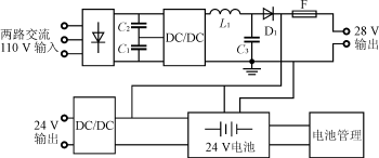
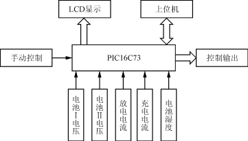
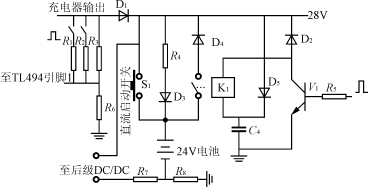
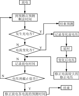
Design of a 24V DC uninterruptible power supply for distribution network 1 Introduction In substations, DC power is important for the secondary equipment of the substation and the real-time communication of the substation. If the DC power supply is unreliable, it will cause the relay protection to fail, resulting in an increase in the power outage area and the communication error, resulting in a larger accident. Therefore, it is required to have higher reliability. Usually, a storage capacitor or a battery is used as a backup power source and directly used as a DC output, but the output power quality is not high, and the battery management is complicated. Therefore, this paper uses a switching power supply with a battery to improve the reliability of the power supply, while the output power quality is high, to meet the communication requirements. Under normal circumstances, battery management is a very complicated task. The system uses PIC16C73 microcontroller to realize battery management, and the management scheme is simple and reliable. 2 24V DC Uninterruptible Power System The schematic diagram of the 24V distribution network dedicated uninterruptible power supply system is shown in Figure 1. Figure 1 Schematic diagram of a dedicated 24V DC power supply system for substation distribution network 2.1 Performance Specifications of the Power System Two-way AC input 90~130V; Can be used for substation small DC motor start-up; Output DC 24±0.03V; Real-time detection of battery operating parameters, remote monitoring; When the load current is 3A, the standby time is ≥10h; Remote management and battery management operations can be implemented on site; Operating temperature range -40 ° C ~ +80 ° C. 2.2 Each module of the power system is fast 1) The previous stage is a half-bridge DC/DC circuit used as a charger. In order to improve the reliability, the input is two-way AC 110V, which can work in AC 90-130V, and the output is DC 28V (the battery is in the state of charge), which is used to charge the battery and start a small DC motor through the battery. The switch tube uses the transistor 2SC2625, and the control chip uses the TL494. Self-excited startup process of the circuit: The voltage divider resistor on the DC bus makes the VBE of the 2SC2625 ≥0.6V, the transistor is turned on, the circuit starts to self-excitation, and the instantaneous voltage is established on the auxiliary group winding, so that the TL494 works and the circuit enters the normal working state. 2) The DC/DC circuit of the latter stage adopts a push-pull circuit structure, and the transformer is bidirectionally magnetized to effectively prevent magnetic saturation [1]. Since the battery terminal voltage can vary between 21V and 27V, the circuit can realize the buck-boost adjustment to stabilize the output voltage at 24V, meeting the load requirements. 3) The battery management module uses PIC16C73, and its block diagram is shown in Figure 2. PIC16C73 is a PIC8 bit mid-range MCU introduced by Microchip. It has only 35 single-byte instructions and comes with 5 A/D conversion modules. It has good stability and can work in harsh environments [2]. Figure 2 Battery Management Block Diagram Through the sampling circuit, the battery terminal voltage, discharge current, charging current, battery temperature, AC power failure, charger fault signal, etc. are sent to the PIC16C73 for processing in real time. The processed data can be sent to the LCD display on site for on-site inspection; the data is sent to the host computer for remote monitoring. 4) Switching power supply integrated controller TL494 can output two complementary pulse control signals, and can also achieve single-ended output. The minimum deadband is 3% and adjustable, with regulated and overcurrent protection op amps. 3 battery management solution and function realization The battery management part of the hardware diagram is shown in Figure 3. Figure 3 Battery management part hardware diagram 3.1 Battery capacity selection According to the requirements of continuous discharge in the state of AC power failure. Under the condition that the manufacturer provides the battery capacity conversion coefficient Kc, the capacity C[3] is calculated by the formula (1). C=IG/(KcδTδK) (1) Where: I is designed according to the maximum load current of the distribution network; G is the independent power supply time of the battery, which is determined by the reliability grade of the distribution network; δT is the temperature coefficient of discharge capacity of the battery. When the temperature increases or decreases by 1 °C at 15 °C to 25 °C, the capacity increases or decreases with the temperature change by 0.006 to 0.007, δT=1+0.006 (T-25) °C); δK is the battery aging coefficient, which is generally 0.8. According to the above principles, combined with practical applications, the system selected two 12A·h/12V lead-acid batteries in series. 3.2 Hardware implementation of battery management After AC power-on, on the one hand, the battery is charged by R4 and D3, and the input is provided for the latter stage. At this time, the relay K1 is sucked, but the battery does not discharge the load due to the reverse bias of D4; in the state of AC power failure or battery discharge, D1 reverse bias, when the battery supplies power to the load through the relay contacts and D4. When the battery voltage is detected to be ≤21V, the power supply is stopped and the system is in a complete power failure state, which should be avoided. R7 and R8 are used to detect the charge and discharge current of the battery. In the state of charge, the 28V DC output is constant, and the output will change when in a discharged condition. 1) DC start In the case of AC power loss, you can directly press S1, the battery is the load power supply, at the same time, the R5 terminal is high level, the relay K1 is closed, even if S1 is disconnected, the power supply will not be interrupted, for S1 Form a self-locking. 2) Discharge control Since the battery is in a state of charge in most cases, this has a great influence on the life of the battery. Therefore, the battery should be discharged for a certain period of time. In this system, the discharge is divided into manual discharge and automatic timed discharge. The length of the timing is determined according to the requirements of the user. Generally, it is set to 60 days. After the internal timer of the MCU arrives, the discharge signal is given. The discharge signal passes through the hardware circuit, and a resistor R1 is connected to the R3 terminal, so that the potential of the pin 1 of the TL494 rises, the control pulse becomes narrow, the output voltage becomes low, and the D1 is turned off. At this time, the battery separately supplies power to the load. The primary DC/DC is equivalent to the no-load state. According to the battery manufacturer's suggestion, the discharge end voltage of the battery is set to 10.5V×2=21V. When the battery voltage is detected to be ≤21V, the discharge signal is cancelled, and the charger charges the battery while providing energy to the load. 3) Motor start-up Since the current required for starting the motor is large, this is achieved by discharging the battery in this system. Before starting, a signal is sent to cause the voltage of the charger to drop, and the battery is put into operation. 4) The charging voltage can be controlled. Changing the charging voltage of the battery means changing the output of the charger. At the R3 end, the different resistors R1 and R2 can be connected to change the output voltage. The user can set the voltage according to the need. 3.3 Battery parameter detection 1) Charging current Ic and discharging current Id When the battery is in the charging state, due to the clamping action of D4, the load current Io is completely provided by the charger. At this time, the terminal voltage of R7 is UR7=IoR7, Id=0, IR8=Io+Ic, Take R7=R8 Ic=(UR8-UR7)/R7; When the battery is powered separately, the clamping action of D4 disappears. At this time, UR8=0, Ic=0, therefore, Id=Io=UR7/R7, so only UR7 and UR8 can get 0~5V through the differential amplifier. The signal is sent to the two A/D conversion channels of the PIC16C73, which can be processed by the microprocessor to detect Ic and Id at any time. 2) Battery voltage Since two 12V batteries are connected in series, the battery terminal voltage should be separately detected, and the voltage output is obtained by resistor voltage division. When it is detected that the battery voltage UB1 (UB2) appears |(UB1-12)|/12≥δ0 (δ0 is the equalization rate, here 4%), it indicates that the battery voltage is not charged uniformly, and corresponding measures should be taken. 3) The battery temperature is measured by the AD590 temperature sensor, and the temperature sampling value is sent to the single-chip microcomputer. When the battery temperature exceeds 80 °C for more than 10 minutes, the discharge control signal is immediately cancelled, and the high level of R5 is changed to low level. Disconnect the relay. 4) Battery capacity Battery capacity detection has always been a difficult problem in battery management. The usual methods are: capacity prediction based on electromotive force, capacity prediction based on battery internal resistance, capacity prediction based on battery internal resistance and electromotive force, and current discharge rate. Capacity prediction, capacity prediction based on current time integration, etc. In this system, since the load change follows Io=0.2n (n is the number of parallel loads), the capacity detection uses the current time integral capacity prediction, which makes the detection simple and feasible. Battery discharge capacity CΔ= 3.4 Prediction of remaining time The purpose of battery capacity prediction is to obtain information about the working time that the battery system can provide. Therefore, in fact, we only need to know the working time that the battery system can provide under current conditions (voltage, current, temperature). At some point, the voltage, current, and temperature values ​​can be measured. Then, we can predict the duration of the constant current discharge of the battery at this current. That is, there is such a table in the system that divides the voltage into several files. The current is also divided into several files, as listed in Table 1. Table 1 Battery Capacity Forecast Table The job of the system is to fill the table and calculate the time the battery can operate at that current based on the terminal voltage and current at a certain time. The size of the voltage and current binning interval determines the accuracy of the battery remaining capacity prediction. The following is a 12A·h/12V lead-acid battery as an example to illustrate the working process of the system. 1) Initialization of the table Initialization can be done by two methods. One is to obtain data from the battery discharge curve provided by the battery manufacturer; the other is to obtain data from the operation. Initializing the data does not require filling the form, but the amount of initialization data determines the accuracy of the remaining capacity predictions at the beginning of the system. We divide the current into 4 steps: 0.05C/0.1C/0.15C/0.2C, and the voltage is divided into 0.1V at 0.1V. 2) Correction voltage The battery internal resistance and polarization voltage are different at different discharge currents. Therefore, it is first necessary to obtain correction voltages under different discharge currents. Based on 0.05C, the battery was subjected to a discharge test to obtain correction voltages at different voltage points. 3) Predicting the remaining time According to the result of the initialization, a part of the data in the prediction table is obtained. If t(V1, I2) is known from the prediction table, the time remaining when the I1 discharge reaches V1 is predicted, and the conversion formula (2) is used. prediction. t(V1,I1)=t(V1-Vx2+Vx1,I2)×I2/I1(2) Where: t(V1, I1) is the time remaining when I1 discharges when the battery voltage reaches V1; Vxn is the correction voltage corresponding to each current. The choice of I2 considers the principle of proximity to ensure the accuracy of the prediction. Select the most recent discharge result to predict, for example: the last discharge with 0.1C, this time to predict 0.2C, then I2 takes 0.1C. This is because the physicochemical state of the battery changes over time, and the closer the time is, the more accurate the result should be. The method predicts that the error of the remaining time is below 15 min, which can improve the measurement accuracy of time and voltage in practical applications and improve the accuracy of prediction. 4) Correction of the prediction table The correction of the prediction table is divided into several cases when the battery is discharged to the cut-off voltage: (1) Before the end of discharge, the battery is subjected to constant current discharge, and the discharge prediction table under the constant current value is corrected; (2) Before the discharge is completed, the battery undergoes several current discharges, and the corresponding voltage prediction tables of these currents are corrected by the time conversion formula (2); (3) Correct at -4mV/°C at different temperatures. Figure 4 is a flow chart of the remaining time prediction program. Figure 4 Flow chart of remaining time prediction program The advantages of this prediction method are: - does not require a large number of preset curves; ——Do not need to add redundant measuring equipment, make full use of the voltage and current measurement system of the original system; - As the running time increases, the accuracy of the forecast increases; - This prediction method can adjust the memory capacity as needed to improve accuracy. 4 Conclusion The DC uninterruptible power supply system introduced in this paper has high reliability, good EMC performance, simple battery detection scheme, convenient control and operation, and the remaining time prediction method is simple and practical. The design of software and hardware is simple and flexible. It works well in the case of use at the substation site.
57 Jack.China RJ11 Jack 1X5P,RJ11 Connector with Panel supplier & manufacturer, offer low price, high quality 4 Ports RJ11 Female Connector,RJ11 Jack 6P6C Right Angle, etc.
The RJ-45 interface can be used to connect the RJ-45 connector. It is suitable for the network constructed by twisted pair. This port is the most common port, which is generally provided by Ethernet hub. The number of hubs we usually talk about is the number of RJ-45 ports. The RJ-45 port of the hub can be directly connected to terminal devices such as computers and network printers, and can also be connected with other hub equipment and routers such as switches and hubs.
RJ11 Jack 1X5P,RJ11 Connector with Panel,4 Ports RJ11 Female Connector,RJ11 Jack 6P6C Right Angle ShenZhen Antenk Electronics Co,Ltd , https://www.antenk.com


![]() Iddt, due to the switching of the load, the current changes according to a fixed law, so CΔ=0.2n1t1+0.2n2t2 (n1t1, n2t2 is the time for different loads). If the initial capacity Co before the discharge of the battery is known, the changed battery capacity Cx = Co - C Δ. This method is relatively simple, easy to implement, and can use the current sampling circuit of the system itself, without the need for special equipment.
Iddt, due to the switching of the load, the current changes according to a fixed law, so CΔ=0.2n1t1+0.2n2t2 (n1t1, n2t2 is the time for different loads). If the initial capacity Co before the discharge of the battery is known, the changed battery capacity Cx = Co - C Δ. This method is relatively simple, easy to implement, and can use the current sampling circuit of the system itself, without the need for special equipment.
The t(n,m) in the table is the time left when discharging with Im and the voltage reaches Vn. Io Ix Im Vo t(0,0) t(0,x) t(0,m) Vx t(x,0) t(x,x) t(x,x) Vn t(n,0) t(n,x) t(n,m) 