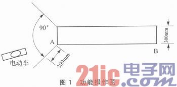
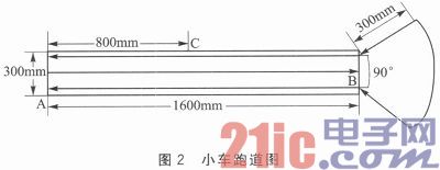
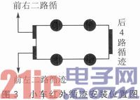
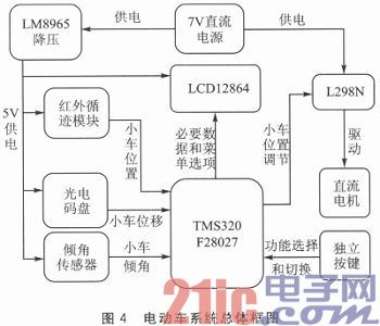
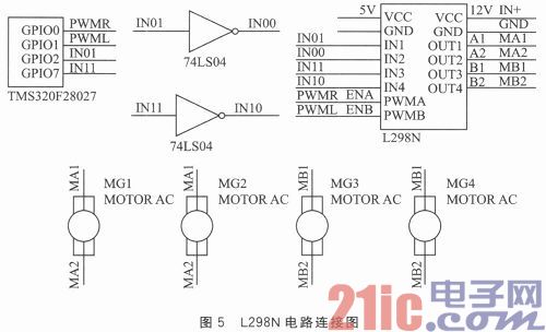
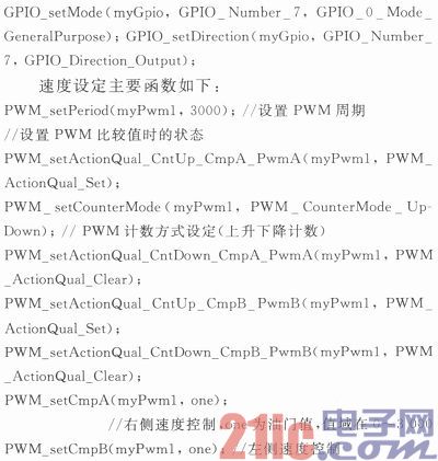
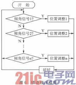
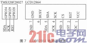
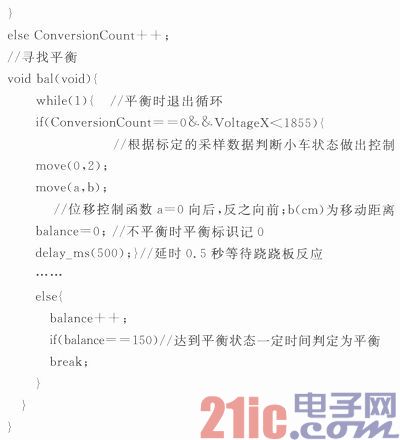
Abstract: This system selects TI's 32-bit DSPTMS320F28027 as the control chip, and designs and manufactures a smart car that can track and find balance. Hardware design and programming of the car is based on the position markers on the given runway and runway. The track is divided into four tracks before and after, and the 4-channel infrared tracking module is used to ensure that the car can move forward and backward on the designated route. This article refers to the address: http:// Key words: TMS320F28027 chip; infrared tracking; tilt sensor; analog to digital converter introduction This system selects 32-bit TMS320F28027 as the control center of moving objects. The TMS320F28027 is rich in resources, with a 32-bit architecture, advanced peripherals, high analog integration, up to 128 KB of flash memory, and features such as powerful ADCs, high-resolution PWM, and wet-enhanced capture units. Excellent components, high-precision on-chip oscillator, analog comparator, power-on reset and power-down protection. This paper takes the design of electric vehicle raft as an example, introduces the operation and control of PWM motor speed regulation, A/D sampling, interrupt and I/O port of TMS320F28027, and the connection of external expansion hardware such as LCD, L298n and infrared tracking. Tips and methods. 1 car function introduction 1.1 Buttons and display functions Key operation: use 3 buttons to select, confirm, and exit function operations. After the system is powered on, the display interface enters the main menu. Through the “Select†button 埘 “Board balance†and “Upper board balance†Select the function, press the “confirm†button at the end of the selection, and the system enters the corresponding function. At this time, you can press the “Exit†button to exit the corresponding function. Display function: LCD displays the tilt angle of the car and the function being executed by the car in real time. After successfully completing an operation, the LCD gives an indication of “OKâ€, and at the same time, the time taken for its operation is displayed during each operation, and all tasks are displayed. The time spent on each operation. 1.2 “On-board balance†function In the absence of counterweight, the electric vehicle completes the following movements: 1 The electric vehicle starts from the starting end point A and travels quickly to the vicinity of the center point C; 2 The electric vehicle is in equilibrium near the center point C as soon as possible, maintaining balance for 5 s, and giving a clear balance indication; 3 The electric vehicle starts from the equilibrium point in step 2 and travels fast to the end B of the seesaw (the front end of the vehicle is not more than 50 mm from the end B); 4 After the electric vehicle stops at point B for 5 s, it quickly reverts back to the starting end A to complete the entire journey; 5 During the entire driving process, the electric vehicle is always on the seesaw, and the time taken for the electric vehicle to travel is displayed in real time in stages. Among them, the infrared tracking device is completed near the point C and back to the point A, and the tracking flag is completed. The balance is mainly detected by the tilt sensor to detect the state of the car before and after the car is moved. 1.3 “Upper board balance†function The weight is fixed at any specified position within the adjustable range, and the electric vehicle completes the following movements: 1 Place the electric vehicle on the ground at a specified position within the sector of the 90° fan-shaped area, 300 mm away from the starting point of the raft (the head is facing the raft), and the electric vehicle can automatically drive up the raft, as shown in Figure 1. 2 The electric vehicle is balanced on the seesaw, giving an obvious balance indication and maintaining a balance of more than 5 s. 3 Place another block weight of 10% to 20% of the mass of the electric vehicle in the position specified between A and C as shown in Figure 2. The electric vehicle can rebalance and give a clear balance indication. Balance for more than 5 s. 1.4 Runway and trolley introduction (1) trolley track The runway is divided into two parts: the seesaw of the rectangular part and the ground area of ​​the sector. The arrows on both sides of Figure 2 represent the tracking marks, and the middle arrow of the seesaw is the trailing tracking mark. Place the seesaw bracket at point C in the middle of the seesaw to ensure that the seesaw can swing freely. (2) Car tracking module installation position It mainly introduces the installation position of the car tracking module to ensure that the car can track correctly. The forward tracking is completed by two infrared tracking devices on the left and right sides of the front of the trolley, and the position is matched with the forward tracking line on the raft. The retraction tracking is completed by the 4-way infrared tracking device at the rear of the car, and the position is matched with the back plate to follow the trace installation. The installation location is shown in Figure 3. 2 function module circuit connection 2.1 System overall model TI's 32-bit DSP TMS320F28027 is the control chip of the system. The system supplies power to the motor through a 7 V regulated DC power supply. At the same time, the 7 V regulated power supply supplies power to other modules after outputting 5V voltage through the LM8965 voltage regulator module. After power-on, use the independent button to match the LCD12864 to achieve function selection. When the function is selected, the car will reach the designated location under the guidance of the infrared tracking module to start searching for balance. At this time, the system will A/D sample the output voltage of the tilt sensor and transmit the data. The chip is processed, and then the chip output signal is adjusted to the L298N-driven DC motor, and the photoelectric code wheel is used to control the trolley to move on the seesaw to achieve balance point finding. The system block diagram is shown in Figure 4. 2.2 L298N drive connection circuit L298N is a double H-bridge DC motor driver chip, which mainly adjusts the PWM speed of the DC motor and performs PWM subdivision operation on the stepper motor. The terminal voltage Vs of the driving part is +5 to +35 V, and the maximum current is 2 A; the operating voltage of the logic part is 5 to 7 V, the current is 0 to 36 mA, and the effective value of the low level is -0.3 to 1.5 V. The active high value is 2.3 V to Vss. The driver board can drive 2 DC motors. The ENA and ENB are enabled when the enable level is high. Set the input levels of IN1 and IN2 to determine the rotation direction of the motor, and change the duty cycle of the input enable PWM pulse to achieve speed regulation. . (Note: When the enable signal is 0, the motor is in the free stop state; when the enable signal is 1, and IN1 and IN2 are 00 or 11, the motor is in the braking state, preventing the motor from rotating.) Since the car uses the left and right speed difference steering, in order to save the I/O port, the motor is connected with an I/O and the enable side controls the steering and speed enable terminals of the two motors on one side to control the speed. /O port controls steering. Specific operation: The two motors on the same side are connected in parallel. One end of the motor is controlled by L298N through the I/O port, and the other end leads a signal line from the same I/O port through a non-gate and then controlled by L298N. The specific circuit connection is shown in Figure 5 (where MG1 ~ MG4 are 4 DC motors). The main functions of the direction setting are as follows: The tracking function can be realized by the tracking module. The tracking module is divided into four front and rear channels. The four signal ports of the first four channels are connected in parallel with the last four channels. The four infrared tracking modules of the first four channels are powered by one I/O port, and the last four channels are powered by this I/O. The mouth is supplied by a non-door. Simply change the high and low levels of this I/O to complete the switching of the tracking module. The tracking program block diagram is shown in Figure 6. The main procedures for tracking are as follows: 2.3 LCD12864 circuit connection In order to save the I/O port, the LCD selected for display is SPI transmission type, mainly used for necessary data display and menu and system status display. The module has a total of 10 pins, including the power and empty pins and RET pin for power-on reset, CS pin transfer master-slave state selection, SCK pin clock signal input, SDA pin data input The BUSY pin is busy interface. Due to the limitation of the I/O port, we are not using the SPI data transmission mode, but the analog SPI data transmission. The analog SPI is mainly to simulate the data transmission timing. Analog SPI data transmission, only one bit of transmission of data. Because this timing is triggered by a rising edge, the clock signal is deasserted before transmission and is set high after the end of the transmission. However, the programming of the program is cumbersome because the commands and data of this LCD are 8-bit data. So choose to input 8-bit data by bitwise and shifting. The specific procedure is as follows: In actual operation, it is necessary to reset the LCD every time the power is turned on (RST is set low for about 10 ms, then set high for about 20 ms) to ensure the LCD is displayed normally, and the LCD needs to be initialized before command and data transmission. Operation, that is, clearing the LCD (clearing the garbled display for a moment of power-on), and then setting the brightness according to the requirements. Since the LCD only needs to receive data in this design, the CS chip selection terminal is directly grounded, and the LCD is set as the slave input device. The specific circuit connection is shown in Figure 7. 2.4 Inclination sensor circuit connection The tilt sensor uses the MMA7361 for digital signal transmission. This module can detect the X/Y/Z triaxial tilt angle of the device and the acceleration during the period. The car needs to find the balance on the seesaw by only one axis to detect the inclination, so the optional one axis is parallel to the car face and can be pointed vertically to the front. When the car is tilted back and forth, the output voltage changes, and the linear change of the output voltage reflects the inclination of the car, the acceleration of the motion, and the direction of motion. The corresponding voltage/angle, voltage/acceleration conversion is performed by A/D sampling, so that the attitude of the trolley can be adjusted at all times. The tilt sensor A/D sampling program is set as follows: Conclusion This article only uses some of the functions of TMS320F28027, the algorithm is relatively simple, just for everyone's learning exchanges. TMS320F28027 has a lot of powerful features that are waiting for everyone to learn and use. Personal experience shows that the TMS320F28027 is fast and easy to learn. It is not only suitable for amateur electronic design, but also meets most of the needs of professionals. It is a cost-effective chip. In conjunction with the use of external expansion hardware, the electrical parameters of the TMS320F28027 and hardware modules should be carefully read to prevent component damage. Volvo Generator Set,Move Diesel Generator,Heavy Duty Genset,Silent Genset Yangzhou Hengyuan Electromechanical Equipment Co., Ltd. , https://www.lchypower.com