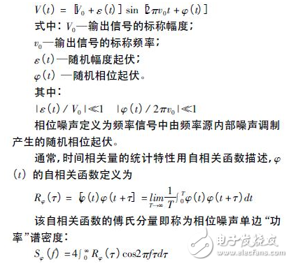
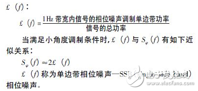
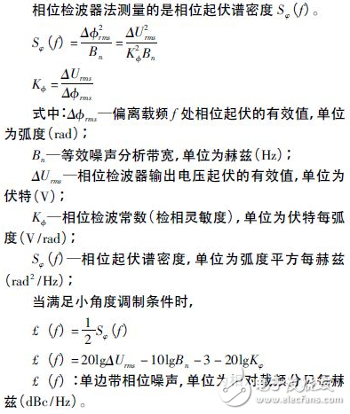
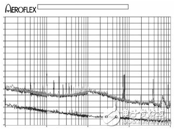
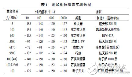
1 Introduction Phase noise is an important indicator of frequency source and frequency control devices. The test of frequency source phase noise is a common work of time and frequency professional metrology testers. There are a lot of articles to introduce, but the phase noise of frequency control devices, that is, the test of additional phase noise, is rarely mentioned in the article. This paper briefly introduces the definition of phase noise, introduces the test process of additional phase noise in detail, gives the actual test results, points out some precautions in the process of additional phase noise test, and hopes to have certain phase noise testers. Learn from the meaning. 2 frequency source phase noise definition The output signal of the frequency source can generally be expressed as: In phase noise measurement, the actual test result is not the spectral density defined above, but the ratio of signal modulation sideband power to total signal power. According to the definitions recommended by the international community in the early years and the NIST of the National Institute of Standards and Technology in recent years, the single-sideband phase noise is used as the frequency domain representation of frequency stability. 3 frequency control device additional phase noise definition The frequency control device adds phase noise, also known as two-port component noise or residual noise. When the signal passes through the two-port component, the noise is applied to the signal in a linear addition or multiplication (modulation). Two-port components include amplifiers, dividers, filters, frequency multipliers, and the like. 4 additional phase noise measurement The additional phase noise is measured using the phase detector method. The phase detector method is a phase noise measurement method with the widest application, high sensitivity and wide analysis range. It is named because the phase detector is used to convert the phase fluctuation of the signal into voltage fluctuation, and then the Sφ(f) is measured by a spectrum analyzer. Therefore, the method utilizes the characteristic that the two input signals of the phase detector are sensitive to the phase of the signal when they are at a phase difference of 90°, so it is also called a quadrature phase detection method. Therefore, the method must have a reference frequency source, also known as the dual source method or the active method. This measurement method is used to measure high-stability, low-noise precision frequency sources such as atomic frequency standards, high-stability crystal oscillators, low-noise frequency synthesizers, phase-locked sources, and various frequency control devices. The basic test principle of the phase detector method for testing additional phase noise is to divide the signal under test into two paths for phase detection. When the two signals are orthogonal and the electrical lengths are equal or approximately equal, the amplitude modulation noise and the source noise are fully suppressed. The output of the phaser reflects the additional phase noise of the frequency control device being measured. 4.1 Measurement block diagram The additional phase noise measurement block diagram is shown in Figure 1. Figure 1 Additional phase noise measurement block diagram 4.2 Measurement steps (1) Measurement preparation Connect the instrument according to the diagram, warm up and warm up, and the warm-up time is as required by the instrument manual. Note that the delay difference between the two signal paths from the power splitter to the phase detector should be the smallest, and a frequency source with small amplitude modulation noise is selected. (2) System calibration The system calibration is to measure the phase detection coefficient Kφ and determine the relationship between the phase fluctuation of the input signal and the fluctuation of the output voltage of the phase detector. There are two common methods for system calibration, positive and negative DC peak method and beat method. Positive and negative DC peak method. Adjust the phase shifter and observe the orthogonal indicator so that the DC voltage output from the phase detector reaches a positive peak, expressed by Umax, and then adjust the phase shifter to make the voltage reach a negative peak, expressed by Umin. Kφ=(Umax-Umin)/2 The beat method. Use the power meter to measure the power of the reference input; set the output frequency of the frequency synthesizer to f0+fb (fb can be set to any low frequency less than 100kHz, typically 1kHz), and the output power is equal to the reference input power. Instead of the original reference signal being connected to the reference input terminal, the replaced signal path is terminated with a 50Ω terminal load, and the measurement system measures the voltage peak of the beat signal fb output by the phase detector, and the value of the phase detection constant K? is equal to the voltage peak of fb. . (3) Orthogonal and measurement The phase shifter is adjusted so that the DC voltmeter reads zero, that is, the system is orthogonal, and the sideband level value Pm at the carrier frequency f is measured by the spectrum analyzer. (4) Correction of measurement data The measurement value Pm of the sideband level is subject to the following three correction factors: 4.3 Test Results Example Figure 2 shows the actual test results for our solid state power amplifier. The bottom curve in the figure is the noise floor of the PN9000 phase noise test system. The top three curves are the results of three repeated measurements. Figure 2 Example of additional phase noise measurement results 4.4 Notes (1) Under the premise of maintaining orthogonality, try to make the electrical lengths of the two input signals of the phase detector equal, and the noise of the source cancels each other in the phase detector, and the measured phase noise is the frequency control of the measured frequency. Phase noise of the device. (2) Currently, only the PN9000 phase noise test system with the additional phase noise option and the HP3048A phase noise test system have additional phase noise test functions. (3) Before testing the additional phase noise of the frequency control device, it is generally necessary to first measure the noise floor of the system to ensure that the test system works normally. (4) The phase noise of the frequency control device is generally better than the phase noise of the signal source. The phase noise of the solid-state power amplifier we tested is much better than the phase noise of the signal source. 5 amplifier description of the degree of signal degradation For the additional phase noise test of the amplifier, I have tried to measure the phase noise of the signal source first, then measure the phase noise of the signal source after the amplifier is connected, and characterize the performance of the amplifier by the degree of deterioration of the phase noise of the signal source, but the result It is almost impossible to see the deterioration of the signal source by the amplifier. After the analysis test results are true, this test method tests the sum of the phase noise of the amplifier and the signal source. The influence of the amplifier on the phase noise of the signal source can be given by: e(dB)=10lg[1+10-d/10] d is the difference between the phase noise of the amplifier and the source. The deterioration of the phase noise of the amplifier to the signal source is shown in Table 2. Table 2 phase noise deterioration value This method is not suitable for measuring the additional phase noise of the amplifier when the additional phase noise figure of the amplifier is much better than the phase noise indicator of the signal source. 6 Conclusion Additional phase noise metrics for frequency control devices are gaining more and more attention. Proper testing of this metric is an important factor in evaluating the performance of frequency control devices. In this paper, the test process of additional phase noise of frequency control device is introduced in detail. The actual test results are given. Some precautions in the process of additional phase noise test are pointed out. It is hoped that it will be useful for additional phase noise testers. Wired Barcode Scanner,Wired Scanner,Wired 2D Barcode Scanner,Barcode Scanner Usb Cable ShengXiaoBang(GZ) Material Union Technology Co.Ltd , https://www.sxbgz.com