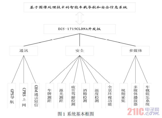
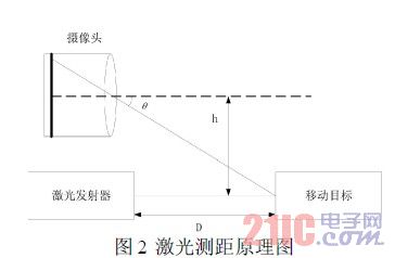
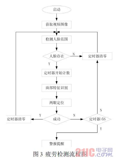
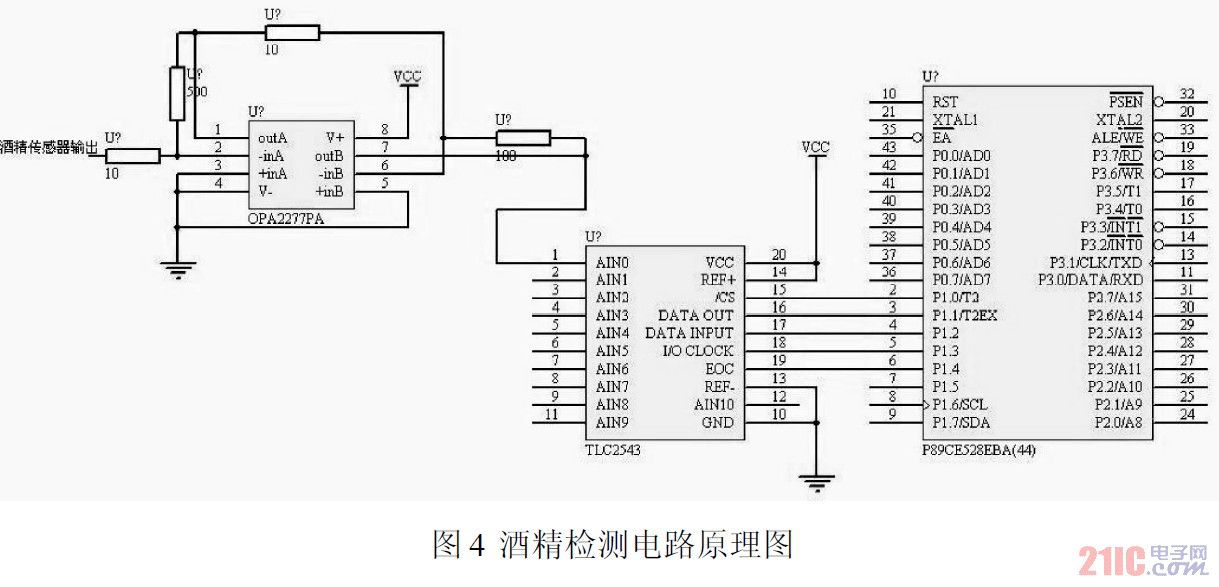
2.1 Development Platform This article refers to the address: http:// The system uses EC5-1719CLDNA development board as the platform, EC5-1719CLDNA supports Intel CoreDuo/Celeron M low-power processor, integrated graphics processing core by Intel945GM chipset, supports VGA, LVDS, DVI, TV-OUT multiple display and double The screen shows that there is 1 PCI-104, 1 PCIE×4 expansion bus, 4 USB2.0 interfaces, and 2 SATA interfaces. The development board expands the rich peripheral hardware devices, and uses the powerful algorithm technology of image processing open source code opencv, combined with signal processing technology, to fully utilize the high-speed CPU performance of this development board. 2.2 System framework This system function is divided into three major areas: security, communication, and multimedia. Safety includes license plate ranging, laser ranging, fatigue driving detection, panoramic surround vision system (AVM), alcohol concentration detection and temperature detection. Communication includes GPRS Internet access, GSM calls, GPS navigation, multimedia, media players, including in-car entertainment systems, Video capture. The system block diagram is shown in Figure 1. 2.3 Basic functions The system realizes functions such as laser ranging, fatigue detection, alcohol concentration detection, GPS positioning, and panoramic viewing. Laser ranging is to measure the distance between the car and the cars that may exist on the left and right sides to determine whether it is safe or not. Fatigue detection is to monitor the closing time of the human eye. If the driver is tired for more than a certain period of time, an alarm sound is emitted. The alcohol concentration test is to test the alcohol concentration in the air, and an alarm is issued if the alcohol concentration exceeds the standard. GPS positioning embeds the GPS system into the system for GPS positioning. The panoramic surround system installs 4 cameras around the vehicle, and uses four cameras to view the scene in real time. The images collected by the four cameras are combined and displayed on the display screen of the cab. The driver can understand all the conditions around the vehicle at a glance. Improve the overall safety factor of the car. 3 function realization 3.1 Laser ranging function realization The schematic diagram is shown in Figure 2. It is assumed that the laser beam is completely parallel to the optical axis of the camera, and the center point of the laser beam is the brightest point in the camera field of view. The camera captures this point as the laser beam strikes the tracking target in the camera's field of view. Easy to derive the distance D: Where: Num is the number of pixels from the center of the image to the drop point, Rop is the radians of each pixel, and Offet is the radians error. The algorithm flow is: first, start the camera, capture the video image through the camera, intercept the image; find the bright spot indicated by the laser through the bright spot detection program, if it exists, measure the number of pixels from the center of the image Num; finally, calculate the spacing by the formula, By comparing with the set safety distance, it is determined whether it is safe, and if it is not safe, an alarm reminder is issued. 3.2 Fatigue driving detection function realization Studies have shown that when people are sleepy, the blinking speed is slower and the blinking duration is longer. The system determines whether fatigue occurs by extracting the length of the driver's closed eyes. By detecting the face range, determining whether the face exists, if not, the timer is cleared and returned; if the face is detected, the timer starts, and counting starts; meanwhile, the facial features are used to locate the two eyes; Can locate two eyes in a certain time slot, prove that the driver is not out of fatigue driving state; at this time, the timer is cleared and returned; if the eye cannot be positioned within 5S, it is considered to be in fatigue driving, and an alarm is issued at this time. remind. The algorithm flow diagram is shown in Figure 3. 3.3 Implementation of alcohol concentration detection function The system uses the alcohol sensor NAP-66E to measure alcohol concentration. NAP-66E has good linearity, wide operating temperature range, and can work normally in a variety of harsh environments. The maximum output voltage is 10mV. Therefore, in order to obtain alcohol, the output of the alcohol sensor must pass through two analog quantities. The stage amplifier is amplified to the voltage value matched with the A/D converter TLC2543. After A/D conversion, the obtained value is properly processed in the MCU, and finally the serial line and the PC communicate, and the measured data is real-time. It is transmitted to the PC, and the PC is used to display and alarm. The alcohol detection chip is used to form an alcohol detection module by connecting with the hardware of the single chip microcomputer, the A/D chip, and the operational amplifier. The design circuit is shown in Figure 4. 3.4 Implementation of GPS positioning function This system uses GARMIN's GPS receiver OEM board - GPS 15H, RS-232 output, interface protocol uses NMEA0183 version 2.00 or 3.00 (optional) ASCII code statement, data update rate is once per second, serial transmission parameters To: Baud = 9600, data bit = 8 bits, stop bit = 1 bit, no parity. The system uses the serial port to receive data when reading GPS data. The software implementation principle is as follows: Use the initial initialization, set the serial port used, the corresponding baud law is 9600, the data bit is 8 bits, and the stop bit is 1 bit. After the user clicks the receive button, the query method is used to read some strings after the GPRMC (Global Position RecomendedMinimum Specific) from the 1 0 2 4 bytes, and the data valid bits of the program are included in the GPRMC, and the latitude is included. And longitude, the data format is as follows: $GPRMC, <1>, <2>, <3>, <4>, <5>, <6>, <7>, <8>, <9>, <10>, <11>, <12> , <13> <1> Current location of Greenwich Mean Time, format is hhmmss <2> Status, A is the effective position, and V is the non-effective reception warning, that is, the number of satellites above the current antenna field of view is less than 3. <3> Latitude, format is ddmm.mmmm <4> indicates the northern and southern hemispheres, N is the northern hemisphere, and S is the southern hemisphere. <5> Diameter, format is dddmm.mmmm <6> Mark the east and west hemispheres, E for the Eastern Hemisphere, and W for the Western Hemisphere <7> Speed ​​on the ground, ranging from 0.0 to 999.9 <8> Future data is not used. In order to receive data conveniently, the corresponding software is used to mask out unnecessary statements, leaving only the GPRMC statement. Since the GPS module obtains valid data in about 90 seconds in the open air after power-on, the 13th bit after finding the G in the GPRMC is the data valid bit. When 'A' is judged, the next 9 bits are read as the latitude display from the 17th bit in the data segment, and the subsequent 10 bits are read from the 29th bit as the longitude display. The received GPS latitude and longitude is then automatically invoked by the appropriate conversion to map the location in the library, and the current location is indicated by a red dot on the map. 3.5 panoramic view function The panoramic surround system has four cameras mounted on the front grille, left and right side exterior mirrors and tailgate of the vehicle. The camera has a wide-angle lens for real-time wide-angle photography. The software is developed with the DirectShow development kit. With Di rectShow, the application can be easily captured from the capture card that supports the WDM driver model, and then post-processed or even stored in a file. 1 Introduction Since the 21st century, the automobile industry has played a leading role. At the same time, the proportion of electronic equipment in manufacturing costs has increased from 16% to more than 30%. In 2010, the proportion of automotive-equipped vehicles will reach 40%. In the future of automotive electronics, components and their peripheral products around safety, energy saving, environmental protection, comfort and entertainment will develop faster. In this context, this paper designs and develops an intelligent vehicle security system based on image processing technology. 2 System Introduction Disposable Vape Pen,Disposable Vapor Pen,Disposable Vapes,Vape Disposable Pod Shenzhen Xcool Vapor Technology Co.,Ltd , http://www.xcoolvapor.com


