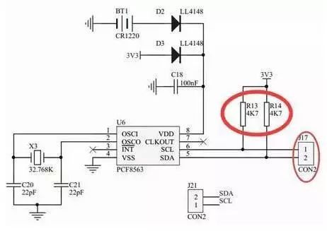
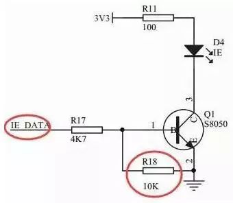
Baidu pull-up resistors and pull-down resistors, a bunch of explanations came out, but it seems that there is no explanation of the familiar, it may be the level of people who write explanations is too high, so if the Xiaobian can not hear understand. Let me give you a quick and easy explanation. Make sure you understand! Pull-up resistor and pull-down resistor used in what occasion? A: Used in digital circuits where high and low levels exist. How to connect the pull-up resistor and pull-down resistor? Pull-up resistor: one end of the resistor is connected to VCC, and one end is connected to a logic level access pin (such as a microcontroller pin) Pull-down resistor: Connect one end of the resistor to GND and one end to the logic level access pin (such as the microcontroller pin) As shown in the above figure, R13 and R14 have one end connected to 3.3V and one end connected to the pin of the microcontroller through J17. These two resistors are pull-up resistors. As shown above, one end of R18 is connected to GND, and the other end is connected to the pin of the microcontroller (it is only connected to the pin of the microcontroller after connecting a resistor). So this is a pull-down resistor. What are the use of pull-up and pull-down resistors? Improve driving ability: For example, with the microcontroller output high, but due to the influence of the follow-up circuit, the output is not high, that is, VCC can not be achieved, affecting the circuit work. So pull on the pull-up resistor. The reverse case of the pull-down resistor causes the microcontroller pin to output a low level. As a result, the output circuit of the follow-up circuit does not reach the GND level, so a pull-down resistor is connected. When the microcontroller pin is indefinite, let the back of a stable level: For example, in the case of a pull-down resistor, the level is indefinite when the microcontroller is powered on. If there is a microcontroller connected to the power supply after the power is turned on, the microcontroller pin is an input pin instead of an output pin. At this time, the level of the SCM is also uncertain. The function of the R18 is to force the level to remain at a low level if the pin level of the previous SCM is indefinite. Let me explain this again. If IE_DATA is not connected to any of the pins, IE_DATA will be low due to the pull-down effect of R18, so the transistor will not be turned on. Hall Closed Loop Current Sensor Hall Closed Loop Current Sensor,Closed Loop Current Sensor,Hall Effect Current Transducers,Closed Loop Hall Current Sensor Zibo Tongyue Electronics Co., Ltd , https://www.tongyueelectron.com
