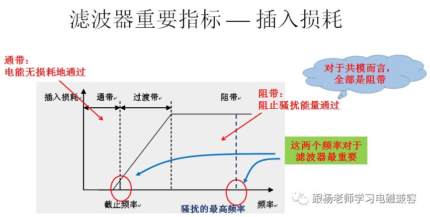
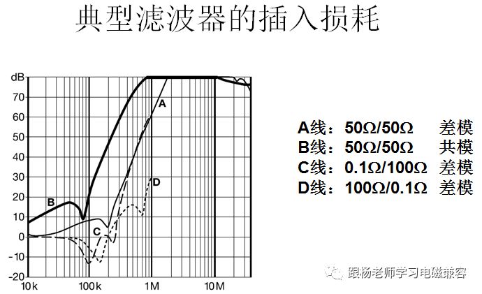
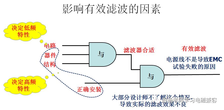
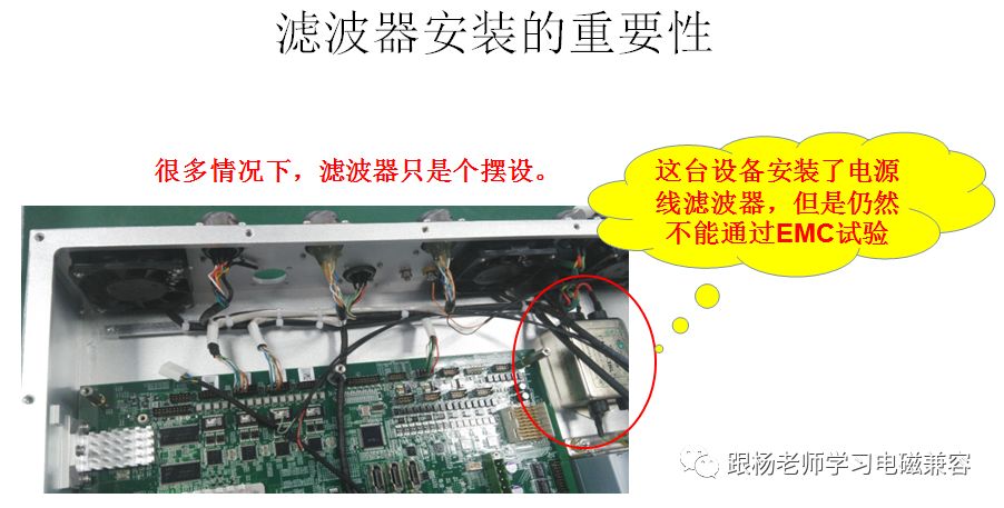
How do you choose the filter in your product design? The power line is equivalent to the gate of a community. The security of the community is closely related to the guard. The power line filter is equivalent to the security of the community gate. The power line without a filter is equivalent to a door without security and without any protection. Therefore, a filter must be installed on the power line of the electronic device. The power line filter allows the power used by the device to pass through, blocking the passage of excess harassment energy. The middle diagram is the shape of the power line filters, which are common in the market. The power line filter is a bidirectional device, that is, it can prevent external harassment from entering the interior of the device, and can also prevent harassment inside the device from being conducted along the power line. Therefore, the power line filter is indispensable for smooth passage of conducted emissions, radiated emissions, conducted sensitivity, and radiation sensitivity tests. The effect of the power line filter is represented by the insertion loss, which is similar to the shielding effectiveness of the shielding material, and refers to the degree of loss of the signal current flowing through the filter by the filter, expressed in dB. Power line filters are low-pass filters. The so-called low-pass filter, the low-frequency insertion loss is small, allows the passage of lower-frequency current, high-frequency insertion loss, blocking the passage of higher-frequency current. This is because the power supply voltage of the electronic device is generally low in frequency, and the electromagnetic disturbance is generally high in frequency, so the filter allows the operating current to pass and prevents the disturbance current from passing through. The range from the passband to the stopband is called the transition zone. The frequency at which the loss of the signal to the filter is equal to 3 dB is called the cutoff frequency of the filter, which means that beyond this frequency, the insertion loss of the filter is already large and it begins to affect the passage of normal energy. It should be noted that the insertion loss of the filter is divided into differential mode insertion loss and common mode insertion loss because the conducted disturbance emission has both differential mode current and common mode current. When considering differential mode insertion loss, we need to pay attention to the passband characteristics of the filter because the operating current of the device is differential mode. That is, the filter cannot generate excessive losses in the power supply voltage, which can affect the normal operation of the device. For common mode insertion loss, we do not need to consider the characteristics of the passband. The ideal common mode insertion loss is infinite in the whole frequency band, because all common mode currents are disturbance energy. This is a typical power line filter insertion loss diagram. There are four curves in the figure. Curve A is the differential mode insertion loss, which is the result of measurement under the condition that the impedance of the network connected to both ends of the filter is 50 W. Curve B is the common-mode insertion loss, which is the result of the measurement under the condition that the impedance of the network connected to both ends of the filter is 50 W. Curve C is the differential mode insertion loss, which is the result of measurement at a condition where the impedance of the network connected to one end of the filter is 0.1 W and the other end is 100 W. Curve D is the differential mode insertion loss, which is the result of the measurement at a condition where the impedance of the network connected to one end of the filter is 100 W and the other end is 0.1 W. It can be seen from the figure that the insertion loss represented by curve C and curve D is obviously inferior to curve A. This shows that the insertion loss of the filter is related to the impedance of the network connected to both ends of the filter. Both cases of curve C and curve D represent the worst case, ie, the insertion loss of the filter will not be worse than these two cases. Please note that curve C and curve D have a negative insertion loss value around 100 kHz, which means that the filter will not only attenuate harassment, but it may also increase harassment. In the figure, the logic diagram is used to draw the conditions required to achieve an effective filtering state. The "AND" in the figure represents two conditions at the same time and there will be one result. . First of all, look at the “AND†on the right side. In order to achieve effective filtering, not only the performance of the filter itself is required, but also the correct installation method of the filter is required. This is a special kind of filter. Many designers are unaware of this particularity. They think that as long as the method of using ordinary electronic devices is used, wires can be used to connect the filter to the circuit without paying attention to the installation method. As a result, the filter is installed on the power line of the device. But did not achieve the desired results. Look at what conditions are needed to form a suitable filter. This is reflected in the "and" on the left. It can be seen from the figure that the performance of the filter itself is not only related to the circuit form and device parameters of the filter, but also related to the type of device, the assembly method of the filter, and the structure of the filter. In general, the circuit form, device parameters, etc. only determine the low-frequency characteristics of the filter, and the type of the device, the way the circuit is assembled, and the structure of the filter determine the high-frequency characteristics of the filter. Therefore, the designer needs to establish a concept. That is, the two circuits have exactly the same filter, and their high frequency characteristics may also vary greatly. Earlier we discussed the conditions needed to achieve effective filtering. It is important to know that the filter is installed. In fact, in many cases, the filter is installed as shown in the figure. At this time, the filter can only filter the lower frequency, but does not filter the higher frequency. The high-frequency characteristics of the filter are important for many tests, especially for the stringent requirements of the RE102. We learned about electromagnetic shielding in advance, where we have repeatedly emphasized the influence of the conductors that pass through the shield on the shielding effectiveness. The filter is mounted in the state shown in the figure. The power cord forms a conductor that passes through the shield, which can cause the shield to leak. The filter can only play its due role if it is properly installed. If it is not installed correctly, no matter how good the filter will not work.
Indoor Fixed LED Display is a popular product for its high quality, every year sold to at least 80,000 pieces around the world, including Europe, North America, southeast Asia.Compared to other indoor LED display in the market, its biggest advantage is that it can display high-definition images while maintaining low power consumption.Besides, it adopts Die casting aluminum cabinet which is ultra-thin and ultra-light and owns good heat dissipation.Easy to install and maintain and suitable for multiple indoor scenes.
Application:
Movie theaters, clubs, stages.
Indoor Fixed LED Display,Led Wall Display,Video Wall Display,Outdoor Led Screen Display Guangzhou Chengwen Photoelectric Technology co.,ltd , https://www.cwleddisplay.com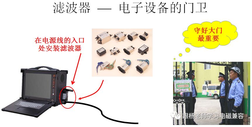
* Business Organizations:
Supermarket, large-scale shopping malls, star-rated hotels, travel agencies
* Financial Organizations:
Banks, insurance companies, post offices, hospital, schools
* Public Places:
Subway, airports, stations, parks, exhibition halls, stadiums, museums, commercial buildings, meeting rooms
* Entertainments: