With the rapid development of IT technology, electronic technology, communication technology, and automatic control technology, high-speed real-time acquisition of industrial field data has become an inevitable part of the development of electronic products and industrial control technology. The hardware circuit of the entire acquisition system is shown in Figure 1. Firstly, the 12-channel signal is modulated by a multi-channel modulation circuit, which includes corresponding signal conversion, anti-interference, and preliminary signal processing, so that the collected signals of each channel can meet the requirements of the ARM9 core for signal acquisition. After multi-channel selection and ADC sampling, enter the ARM9 core. In order to realize real-time monitoring, real-time control and real-time adjustment of the working state of the whole system, the upper computer monitor and the live display touch screen are set, and all the information required to be displayed by the user is displayed on the upper computer or output synchronously on the live LCD. The sampling is divided into three frequency bands: high frequency band (300~200 ksps), medium frequency band (200~100 ksps), and low frequency band (less than 100 ksps) according to the sampling frequency band, and each frequency band is composed of four external sampling channels. The communication between the ARM9 core and the host computer is realized by using UART and RS232 conversion circuits. The system working power supply is supplied by a unified power supply, and provides power support for the PC and the ARM9 core and the corresponding working circuits after the voltage conversion is realized. Figure 1 data acquisition system hardware circuit The software design principle of the system is shown in Figure 2. The 12 channels of acquisition signals are multiplexed by the modulation circuit and sampled by the ADC to enter the internal channels of each acquisition task. Each acquisition channel is designed with independent data acquisition, data storage, data processing, and data submission tasks. That is to say, each external acquisition channel corresponds to an independent internal data channel, and the data of this channel is only stored, processed and transmitted in this channel. Each internal data channel task performs a temporal relationship and a priority relationship only during system scheduling, and there is no data coupling relationship. Figure 2 System software design schematic The command scanning part is completed by the independent upper computer and the lower computer scanning task to perform real-time monitoring on the upper computer monitor and the lower computer touch screen. Once the user command is detected, it is immediately sent to the command parsing and processing task, and the task is to the user command. Perform analytical processing. After the command is processed, the extracted result is sent to the sampling channel to be operated by the user, so that it runs according to the user's request. The various frequency band commands within the system are shown in Figure 3. After the command scan function captures the user command, it verifies, analyzes, and extracts the user command, and then sends the extracted result to the command waiting queue of each frequency band in a broadcast manner. If the queue obtains a new command, the user command is sent to each sampling task function under the jurisdiction of the queue, and the user command is immediately executed, including channel switching, changing the sampling period, changing the current task priority, and displaying specific channel data. If no new command is obtained, the sampling task continues to work as it is after waiting for the timeout. This is also an intelligent design, which realizes all functions of viewing, supervising, operating, working state switching, channel switching, parallel real-time acquisition switching from single channel to all channels at any time according to user commands in a very simple way. Switch freely. Figure 3 Internal commands for each frequency band The μC/OSII operating system is a priority-based preemptive operating system, and all tasks must have their own independent and unique priorities [1]. The command scan and data display are set to the highest priority and lowest priority, respectively. The highest priority of the scan function ensures that the user command is responded at any time, and the display task is set to the lowest priority because of its slow speed. As long as the system design is reasonable, and the hunger phenomenon of low priority tasks is properly avoided, the effective information display of the user can be displayed. For command scan and parsing tasks, it is set to the interrupt mode, an interrupt occurs when a user command input is detected, and user commands are parsed, analyzed, extracted, and processed in the interrupt. The commands are broadcasted in the lower half of the interrupt and posted to each sample task function for immediate refresh execution. Because the user works in a different way, the command refresh rate is not high and the task is not large, so it is completely possible to use the fast processing of the interrupt to achieve this function. Figure 4 shows the task working principle diagram In a multitasking design, each task may be interrupted by other tasks at any time. The security, reentrancy, reliability, hunger, interlock, deadlock, etc. of the code must be fully considered. [3] The limit frequency test result received by the host computer super terminal is shown in Fig. 5. Figure 5 limit frequency measurement results The limit frequencies of the high frequency band, the middle frequency band, and the low frequency band were tested separately, and the results were measured under the condition that the CPU usage rate was 80% to 90%. The system successfully realized intelligent design and priority dynamic scheduling, system parameter dynamic setting and other functions, and reached the design index. Tpd Compliant Vapes,Original Onlyrelx Vape,Disposable E-Cigarette Onlyrelx,Vapeorizer Pen Shenzhen Onlyrelx Technology Co.,Ltd , https://www.onlyrelxtech.com
Aiming at the multi-task implementation algorithm in high-speed real-time multi-task data acquisition and the requirements of real-time, effective and high-speed, this paper proposes an intelligent design scheme based on ARM9 and μC/OSII operating system, which realizes task priority dynamic scheduling. Dynamic setting of system working parameters and intelligent design of internal software of the system, system optimization for low-speed peripheral devices, and improved system reliability to improve internal task synchronization. 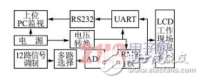
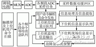
Two data buffers are set for each channel acquisition task in each frequency band. The double data buffer provides a double guarantee for the smooth storage of the sampling task, so that once the sampling work is completed, there is a buffer available, and the data can be stored immediately and then the next acquisition. It also enables subsequent data processing tasks to reduce data waiting time, and can quickly obtain the data that the current sampling channel needs to process, and process and send it to the next level task in the shortest time.
Sampling, data display, and command scanning all involve peripheral devices, which is the slowest running speed of all tasks in the whole system. Setting a double data buffer for sampling tasks can greatly improve the system rate drop caused by slow sampling speed. The optimized design of the display and command scan sections will be described in detail below. 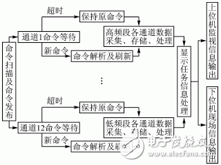
The internal priority setting rule is that the priorities of the three frequency bands of the low frequency band, the middle frequency band, and the high frequency band are successively decreased. The sampling period of the low frequency band is obviously longer than the high frequency band. In the idle time of data acquisition in the low frequency band, the system can smoothly switch the CPU usage right to other tasks, so that other tasks can obtain the CPU usage rights and execute. The priority of each task within each frequency band is decremented from sampling to data storage, data processing, and data submission.
In order to enable the entire system to achieve priority dynamic scheduling, other sampling parameters can also be modified. In the software design, the priority and sampling period of all frequency band sampling tasks are set in the form of global variables before entering the operating system, and defined as volaTIle. The format assigns an independent variable storage address. Then set up an independent scanning task to specifically determine, modify, store and update these parameters. In this way, the system can be operated according to the initialization priority and initialization parameters designed according to the sampling period, and the sampling task priority and sampling frequency of each frequency band and each channel can be set and modified according to the user's own needs. After the modification and confirmation, the modification task will save and update the current system working parameters and exit the operating system, then restart and initialize, the entire acquisition system will start working in a new state. Of course, the user priority and sampling period settings are limited here, and must meet the priority rules mentioned above and the sampling period requirements of each frequency band.
In order to optimize the time scheduling of the entire system, first explain several internal working hours. The operating system tick rate in the i386 system and the Linux 2.5 kernel is set to 1000 Hz [2]. Here, the μC/OSII operating system scheduling time OS_TICKS_PER_SEC is also set to 1000, which means that the task scheduling of the operating system is in ms. The ARM9 core CPU operating frequency is set to 400 MHz, which is the CPU mechanical period in ns. The peripherals include the upper computer command scan and the upper computer, and the lower computer display part work in s. The task switching, scheduling, and delay in the μC/OSII system are all in system beat rate, while the internal code is run in mechanical cycles. The internal task time limit can be in units of beat rhythm or an absolute time difference based on real-time time.
Only the sampling task requires a time limit setting within a single sampling task channel. In order to achieve intelligence, the waiting time delay of the message queue is used instead of the sampling task time limit, and the delay is the sampling period of the channel. Other follow-up tasks include memory development, data processing, and data transmission. They all wait for the upper-level task message in turn, and are not set by the upper-level task. The display task time limit is set to the absolute time difference by ms. 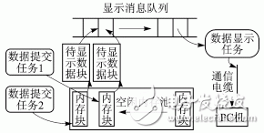
After processing the command scan and sampling tasks, the upper computer and the lower computer display part are affected by the performance of the entire system. The working principle of the display task is shown in Figure 4. The display part is improved by using the message queue provided by the μC/OSII system. Two message queues and a memory block linked list of length 16 are respectively established. After the data submission task obtains the available memory blocks from the free memory pool, the data to be displayed in the task is stored in the memory block, and the memory becomes a band. The data block to be displayed with data. The address of the memory block is then registered as a message on the display message queue. The length of the message queue is set to 16, although only 12 tasks will send messages to the message queue, but in the real-time multitasking program, the running of each task is random, and the number of messages obtained by the message queue in a period of time is not Fixed value, so leave 4 vacancies as margin. Moreover, the initial semaphore is set to protect the message queue. The data submission task detects the semaphore before submitting the data. If the semaphore is valid, the signal can be sent. If the semaphore is invalid, it needs to wait until the available signal is available. The signal can be sent when the bit is in position. At the external hardware operator, an externally sent task sends the message in the message queue to the external signal line at a fixed rate.
In this way, the message queue is equivalent to a buffer, so that all the submitted tasks can send the data to be displayed to the buffer, effectively avoiding the deadlock, competitive risk and other problems caused by multiple tasks contending for a peripheral device. At the same time, the number of tasks is reduced, the number of task switching is reduced, the system time is fully utilized, and system performance is improved.
In order to avoid the above situation, key area protection is performed on the corresponding function body when sending and transmitting messages between tasks, and when the functions are running, interrupt and task scheduling are prohibited to ensure the absolute correctness of data transfer and data sampling. The absolute security of the system operation. 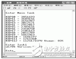
Intelligent design based on ARM9 and μC/OSII high-speed real-time multi-task data acquisition
introduction