This article refers to the address: http:// Acrylic Letter,Acrylic Led Sign,Acrylic Channel Letter,Modern Acrylic Wall Art Wuxi Motian Signage Co., Ltd , https://www.makesignage.com
Digital photo frame is a fashionable electronic consumer product, and also a must-have accessory for the family. It is an electronic product with the core function of storing, playing back and browsing digital photos. At present, most of the digital photo frames on the market are single-chip solutions, represented by ESS/AML0GIC/MPX chip design. In terms of its design process, there is no hardware design in the strict sense but only software design. The core components of the hardware system are off-the-shelf, the functions are determined, the structure is fixed, and the instruction system is immutable, resulting in a limited hardware organization scheme and connection scheme. Therefore, in order to greatly upgrade or expand the system function, it is impossible to upgrade with a simple firmware. A new hardware system must be designed with a better core device.
This paper adopts the SOPC technology based on NiosII soft core processor to realize the design of digital photo frame, which fundamentally changes the shortcomings of traditional design scheme. The Nios II soft core embedded processor is a SOPC solution from Altera Corporation. Nios II is a configurable 16/32-bit RISC processor that combines a rich set of peripherals, dedicated instructions and hardware acceleration units to provide an extremely flexible and powerful SOPC system at a low cost. Developers can integrate themselves according to actual needs. . SOPC technology gives a hardware system design and corresponding software design that involves the underlying layer in electronic design. It has unprecedented degrees of freedom in system optimization, which makes it greatly optimized from multiple angles, multi-factors and multiple structures. Your own design is possible. When the circuit has a small amount of changes, it highlights its advantages, can extend the life of the product on the market, and greatly improve the performance of the multi-function digital photo frame.
1 System overall architecture design and system hardware design Based on NiosII SOPC embedded system development, it mainly consists of three parts: IP library (Nios soft core processor, Avalon bus, peripheral device interface, etc.), SOPC Builder development tool, CNUPro software compilation Device. In addition, the embedded design using NiosII must use Altera's FPGA in hardware. The design in this article uses the EPlCl2Q240C8 chip of Altera's Cyclone series chip.
The multi-function digital photo frame mainly realizes the following functions: can clearly display the automatic play of JPEG pictures and its thumbnail browsing; multi-zone play or picture-in-picture multiple display modes; instant editing and cropping of pictures (rotation, beautification); Excellent audio-visual entertainment, can play MP3, MP4 audio files, real-time subtitle scrolling overlay; file and file browsing and support for USB interface and SD card; a variety of additional function clocks, perpetual calendars, etc. 
The digital photo frame needs clock circuit, CPU, RAM and RAM controller, FLASH and FLASH controller, SD card and SD card control circuit from the overall structure of the CPU to the realization of local functions.
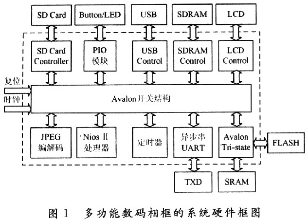
USB interface and USB interface controller, LCD screen and LCD display driver circuit, DMA controller, audio driver and audio control circuit, timer module, system hardware structure diagram shown in Figure 1.
The whole design adopts a top-down design method. The system hardware module is built in SOPCBuilder, and the required functional modules are integrated through the Avalon bus, so that the stability of the system is higher. In addition to the display driver module, audio control module and SD card control module, USB interface control module, other modules can be added IP core build from SOPC Builder.
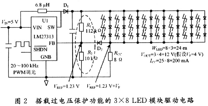
2 LED backlight design LCD panel is the main component of digital photo frame, with white LED for backlighting, LM27313 has been widely used in white LED BLU solution. Figure 2 shows a white LED backlight circuit for an 8-inch digital photo frame LCD. 
When designing an LED backlight driver circuit, the LED is a current-driven device. To ensure the illumination intensity and increase the lifetime of the LED, the most important problem is to maintain a constant current when the LED is forward biased. Since most LED modules are connected to the main board through a connector, the LM27313 will open when it is output due to misoperation or damage to the LED module. There is no signal at the negative input of the error amplifier, and the output voltage will rise without limit. Will have devastating consequences, damage to the LM27313 or the output diode. To solve this problem, an overvoltage protection circuit is added in Figure 2. In Figure 2, resistors R1 and R2 ensure that the constant output voltage does not rise indefinitely by feeding the output voltage to the error amplifier pin (FB).
Dimming control refers to controlling the light intensity of the display according to the preferences of the customer. The LED switch can be controlled by turning the LM27313 on/off, and the switching control of the LM27313 can be achieved by applying pulse width modulation (PWM) on the SHDN pin. The pulse frequency must exceed 20 kHz. Below 20 kHz, the multilayer ceramic capacitor at the output of the circuit will oscillate and produce audible noise.
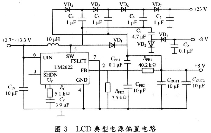
3 LCD Typical Power Bias Circuit Design The DC/DC conversion for LCD flat panel power supplies uses the best power solution LM2622 from National Semiconductor. In a typical LCD flat panel display for digital photo frames, the input supply voltage is approximately +5. OV. A number of different voltages must be provided to allow the display panel to achieve optimum performance through the input voltage, typically using a boost converter. The LM2622 can be used to provide several different output voltages at +5.0 V input voltage. The circuit in Figure 3 shows how the LM2622 should be configured to provide output voltages of +8 V, -8 V, and +23 V, which is very convenient for biasing TFT displays. 
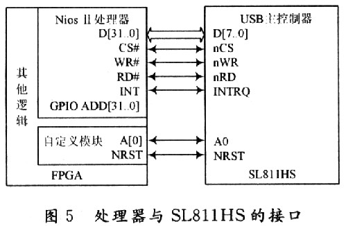
4 USB interface module design With the rapid development of universal serial bus (USB) technology and the expanding application field, it has realized the point-to-point data transmission of USB from PC, and the embedded USB host can complete the point-to-point of USB from the PC. data transmission. The system adopts the scheme of NiosII+USB interface chip. The USB serial interface can be used as a peripheral of NiosII. The interface chip adopts the USB Host/Slave interface chip of SL811HS produced by Cypress. The schematic diagram of the design is shown in Figure 4. 
The SL811HS main controller interface provides an 8-bit data bus and some control signals, such as read/write, chip select, etc., to connect to an external CPU or microcontroller. Also, the L811HS interface provides a simple address line A0 externally that supports programmable I/O or memory map design. Through the analysis of the read and write timing of the SL811HS and the Avalon bus read and write timing, the A0 addressing mode in the SL811HS and the "read/write transmission with a fixed wait slave port" timing of the Avalon bus are used. The address and data of the SL811HS are both By D[7. . O] Time-sharing transmission is distinguished by the level of A0 (data/address selection line). When A0 is set low, D[7. . The address of the SL811HS on-chip register/buffer is transmitted on O], while the high level is data. In A0 mode, SL8llHS normal read and write operations support address auto-add 1 mode, that is, in this mode, the microcontroller only sets the address only once, immediately following the next clock read and write operation SL811HS internal address pointer will automatically jump to Next data location. nWR, nRD, nCS, and nRST are write control lines, read control lines, chip select lines, and reset lines, respectively, which are active low. Nios II completes reading and writing and chip selection of SL811HS on-chip buffer through these control lines. And reset and other operations. INTRQ is the interrupt request signal line. When SL8llHS detects an abnormality such as peripheral insertion, extraction, or data transmission error, timeout, data overflow, etc., it notifies NiosII by setting INTRQ high. The Avalon bus provides a very user-friendly interface. In the interface conversion between the SL811HS and the Avalon bus, the Verilog code only needs to establish the mapping relationship between the SL81lHS port and the Avalon bus port. As shown in Figure 5. 
5 The system software design part compiles the NiosII-based SOPC system and downloads it to the FPGA to generate the hardware system. At the same time, SOPC Builder helps the user to generate the corresponding SOF file. On this basis, the system software design begins. The software part of this system is designed in the software integration development tool IDE provided by Altera Corporation, and is designed in C language and supported by hardware abstraction layer (HAL) function.
The software development sequence is: hardware driver-operating system migration→establishing file system→application design. System software development is done on the Nios II integrated μC/OS-II operating system. Three tasks such as Task_Main (master control task), Task_Gui (GUI graphical human-computer interaction interface display task), and Task_Music (music playback control task) are established in the multi-function digital photo frame system. Using the message mailbox mechanism, the μC/OS-II operating system performs scheduling management for these three tasks.
In order to realize the graphical human-machine interface required by the system, the embedded user graphics system must be designed on the system development platform to establish a human-computer interaction system that meets real-time and rapidity. The Graphical User Interface has always been an important part of the computer, as is the case with embedded systems. In the aspect of embedded GUI, the general embedded graphical user interface software μC/GUI developed by Micrium is selected, which is a special GUI of μC/OS-II operating system, which can realize the perfect combination with μC/OS-II real-time operating system.
6 Conclusion All the hardware structures of the system are integrated under SOPC. The benefits are hardware reconfigurability and reconfigurability, and the top-down design process greatly shortens the system design cycle. Detailed design including LCD backlight circuit, power supply bias circuit, and USB interface module is also introduced. Utilizing the arbitration mechanism of NiosII soft core processor and Avalon bus and the operating system embedded in Nios II, the task scheduling of each functional module is completed, the performance of the whole system is stabilized and improved, and the system design is simplified, which is the field of household electronic products. The development and application has opened up new avenues.
Nios II-based multi-function digital photo frame design
O Introduction