0 Introduction Among the third generation mobile communication technologies, the most representative solutions are CDMA2000 in North America, WCDMA in Europe and Japan, and TD-SCDMA in China. Among them, CDMA2000 is directly evolved based on IS95 (2G CDMA with bandwidth of 1.23 MHz); WCDMA is also called wideband CDMA, and its bandwidth is 5 MHz or higher; TD-SCDMA is also called time-division synchronous CDMA, and its synchronization is mainly It means that the signals of all terminal users' uplinks are completely synchronized when they reach the demodulator at the receiving end of the base station. All of the above three standards are based on CDMA technology. Compared to bandwidth-limited FDMA and TDMA systems, CDMA systems can provide sufficient system capacity, which is mainly limited by the system's interference, and reducing interference can directly increase the system's communication capacity. Since the same-frequency carrier is used for the CDMA system, controlling the power of each mobile station is the key to achieving the maximum capacity, and the interference between the mobile stations can be minimized by the power control technology to achieve the maximum capacity of the channel.
Push Button Switches
The Push Button Switches, also known as the control button (referred to as the button), is a low-voltage electrical appliance that is manually and generally can be automatically reset. The Push Button Starter Switch is usually used to issue a start or stop command in the circuit to control the turning on and off of electrical coil currents such as electromagnetic starters, connectors, and relays.
The On Off Push Button Switches refers to a switch that pushes the transmission mechanism with a button to make the movable contact and the static contact open or close and realize circuit switching. It is a master control device with a simple structure and a wide range of applications. In the electrical automatic control circuit, used to manually send control signals to control connectors, relays, electromagnetic starters, etc.
This Pushbutton Switches is a kind of electric device that is used to switch on and off the small current circuit when the action is released. Generally used in AC and DC voltage below 440V, the current is less than 5A in the control circuit, generally do not directly manipulate the main circuit can also be used in the interconnection circuit. In actual use, in order to prevent desperation, different marks are usually made on the buttons or painted with different colors, and the colors are red, yellow, blue, white, black, green, and the like.
The Momentary Push Button Switch could be divided into metal push button switches and LED Light Switches and ordinary snap button type, mushroom head type, self-locking type, self-resetting type, rotary handle type, with indicator light type, lighted symbol type and key type, etc., with single button and double Buttons. Generally, it adopts a water-storage structure, which consists of a button cap, a return spring, a static contact, a moving contact and a casing. It is usually made into a composite type, and has a pair of normally closed contacts and normally open contacts, and some products can pass. The series connection of multiple elements increases the number of contact pairs. There is also a self-contained button that automatically holds the closed position when pressed, and can be turned on only after the power is turned off.
When the Metal Switches is not pressed, the movable contact is connected with the upper stationary contact. The pair of contacts is called a normally closed contact. At this point, the movable contact is disconnected from the following static contact. The pair of contacts is called a normally open contact: the button is pressed, the normally closed contact is open, the normally open contact is closed, and the button is released. Restore the original working state under the action of the return spring
Push Button Switches,Push Button On Off Switch,Push Button Switch Types,Square Push Button Switches YESWITCH ELECTRONICS CO., LTD. , https://www.yeswitches.com
There are two aspects of power control: from the aspects of power consumption, interference and electromagnetic radiation, the smaller the transmission power, the smaller the power consumption of the mobile phone, the longer the standby and talk time, the smaller the interference to other mobile phones in the same system. At the same time, the cell capacity has been expanded. In addition, the smaller the mobile phone's transmission power, the smaller the interference to other wireless devices, and the smaller the radiation to the human body. On the other hand, in order to ensure the communication quality and hope that the mobile phone's transmission power is larger, such as when the mobile phone is at the far end of the cell, in order to ensure that the mobile phone signal arrives at the base station after long-distance transmission, the signal can still be correctly demodulated, and the transmission power is required. Large enough to overcome the attenuation of the signal over long distances; the mobile phone is also large enough to be transmitted in the wireless shadow area of ​​the building or other occlusion to overcome the multiple reflection, refraction and long-distance transmission of the mobile phone signal. Attenuation; in the case of interference (adjacent channel interference, co-channel interference, blocking, etc.), the transmission power should be large enough to overcome the noise interference. Therefore, the unified expression is: the mobile phone must have sufficient transmission power to ensure communication, and the smaller the transmission power, the better the communication quality is guaranteed.
1 Power control technology and classification In the current mobile communication system, PHS (Personal Handyphone System) rises with its advantages of low construction cost and simple protocol standard. PHS is often referred to as PHS in China. It uses microcellular technology to provide simple and low-cost protocol standards and reduces handset manufacturing costs. The RCR-STD28 standard stipulates that the average transmit power is less than or equal to 10 mW and the peak power is less than or equal to 80 mW. The transmit power is not controllable.
In the second generation mobile communication GSM system, it is stipulated that the mobile phone transmission power can be controlled by the base station. The base station detects the power level of the received signal, and issues a command to control the transmission power level of the mobile phone through the downlink SACCH channel. The adjacent power levels differ by 2 dB, and the mobile station power level and maximum and minimum power are as shown in Table 1. 
The GSM power control rate is relatively slow, and the power control lifting requirements are not very precise and are not very strict. In addition, GSM is far less dependent on power control than CDMA systems. In the CDMA technology-based communication system, power control technology is inseparable. CDMA itself is an interference-limited system, that is, the size of the interference directly affects the system capacity. Therefore, to control the size of the interference, without affecting the quality of communication (QoS), try to make the signal of each MS reach the minimum required SIR when it arrives at the BS, so as to improve the capacity and reliability of the system. Power control can control SIR and effectively overcome and suppress interference. It is one of the core technologies to improve and improve the reliability of 3G cellular mobile communication systems.
Generally, from the perspective of communication uplink and downlink, power control is divided into forward power control and reverse power control. Forward power control is based on the mobile station measurement report, and the base station adjusts the transmit power to the mobile station. Reverse power control is further divided into open loop power control and closed loop power control. The reverse open loop power control is mainly that the mobile station adjusts the transmit power according to the received power variation; the reverse closed loop power control is that the mobile station adjusts the average output power according to the received power control bits.
2 Reverse and forward power control
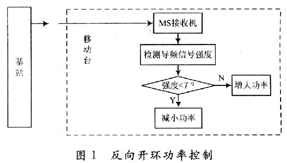
2.1 Reverse Open Loop Control Open loop power control is based on the strength of the pilot signal received by the mobile station to estimate the loss of the forward transmission path to determine the amount of transmit power. It is that the mobile station adjusts the transmit power of the mobile station according to the change of the received power in the cell to achieve the same power at the base station when all the signals sent by the mobile station. It is mainly to compensate for shadows, corners and other effects, so the large dynamic range, according to the IS95 standard, should at least reach a dynamic range of ±32 dB. The control process is shown in Figure 1. 
The main feature of open loop power control is that no feedback information is required. It can respond quickly when the wireless channel suddenly changes, and it can make a wide range of power adjustments. The open loop power control is not accurate enough because the fading estimation accuracy of the open loop power control is based on the consistent fading of the uplink and downlink, while in the frequency duplex mode, the uplink and downlink are The frequency band difference is 190 MHz, which is much larger than the relevant bandwidth of the signal. Therefore, the channel fading conditions of the uplink and downlink are completely uncorrelated, which leads to the accuracy of the open loop power control is not very high, and can only be roughly controlled. effect. The control variance required for open loop power control in the WCDMA protocol is acceptable within 10 dB.
2.2 Reverse Closed Loop Control Reverse power control is closed loop power control when there is base station participation. The design goal is to make the base station quickly correct the open loop power estimation of the mobile station so that the mobile station can maintain the optimal transmission. power.
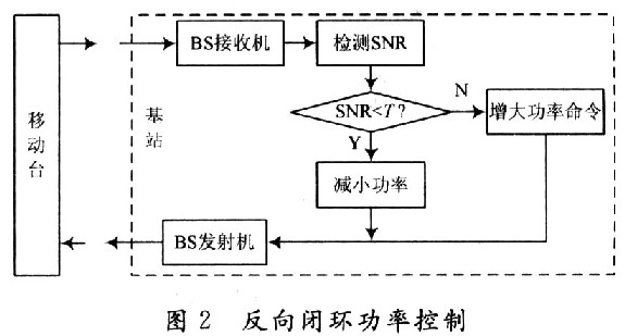
Closed loop power control is done with the assistance of a mobile station. The base station receives the signal of the mobile station, measures its signal to noise ratio, and compares it with the threshold. If the received signal to noise ratio is greater than the threshold, the base station transmits a command to reduce the transmit power on the forward transmission channel. Conversely, a command to increase the transmit power is sent. The control process is shown in Figure 2. 
Closed-loop power control corrects changes in reverse transmission and forward transmission path gain, eliminating inaccuracies in open-loop power control. The base station adjusts the received reverse open loop power estimate of the user terminal to maintain the optimal transmit power of the user terminal. Power control is implemented by inserting power control bits into the traffic channel frame, with an insertion rate of up to 1.6 Kb/s, which effectively tracks the effects of fast fading. However, the adjustment of the closed-loop power control always lags behind the state value at the time of measurement. If the communication environment changes greatly during this time, it may cause the closed-loop collapse, so the feedback delay of the power control cannot be too long, generally by the communication end. The power control commands generated in a time slot should be fed back in two time slots. The closed loop power control consists of two parts: inner loop power control and outer loop power control. In the inner loop closed loop power control, the base station compares the Eb/Io and the target Eb/Io of the reverse channel every 1.25 ms, and then instructs the mobile station to reduce or increase the transmit power so that the channel Eb/Io reaches the target value. The inner loop power control is fast closed loop power control, which is mainly performed at the physical layer between the base station and the mobile station. In the closed loop power control of the outer loop, the base station specifies the target Eb/Io (from the user terminal to the base station) for each frame of the receiver every 20 ms, and when the frame error occurs, the automatic unit of the value is gradually reduced. The period of the outer loop power control is typically on the order of TTI (10 ms, 20 ms, 40 ms, 80 ms), ie 10 to 100 Hz. Outer loop power control can affect system capacity and communication quality indirectly through closed loop control.
3 Forward power control Forward power control means that the base station adjusts the control of the transmit power of each mobile station according to the measurement result of the mobile station. The base station periodically transmits a test, and the mobile station detects the frame error rate of the forward transmission, and reports the statistical result of the frame error rate to the base station. The base station determines to increase or decrease the forward transmission power according to the statistical result of the frame error rate reported by the mobile station. In the process of the base station system slowly reducing the forward link transmit power of the mobile station, when the mobile station detects that the frame error rate (FER) exceeds a predefined value, the base station system is requested to increase the forward link transmit power. The adjustment is made at regular intervals, and the reports of the user terminals are divided into periodic reports and threshold reports. The control process is shown in Figure 3. 
In forward power control, a small forward link power is allocated to a mobile station with a small path fading, and a large forward link power is allocated to those mobile stations far away from the base station and having a high bit error rate. Reasonable allocation of power on each of the forward traffic channels ensures the quality of communication for each user while maximizing the forward link capacity.
4 Conclusion There are many key technologies in the third generation mobile communication system, such as multi-carrier technology, smart antenna technology, software radio technology, multi-user detection technology. Power control technology is one of the core technologies of CDMA system. It enables the system to maintain high-quality communication, significantly improve system communication capacity, and at the same time extend battery life of mobile phones and reduce network construction costs. This paper analyzes the current power requirements in PHS and GSM systems, elaborates the power control in CDMA system, analyzes the control process, its advantages and disadvantages for forward power control and reverse power control technology, and designs the 3G system. Has a certain guiding significance.
The power control capabilities and performance are highly dependent on the accuracy of power measurements and power control command generation and transmission processing delays. Since the signal is Rayleigh fading in mobile communication transmission, the power control system cannot compensate for the change in signal power caused by fast fading, especially when the moving speed of the mobile station is fast, the power control technique will fail. In order to improve the power control technology in CDMA systems, it is ultimately necessary to combine various key technologies to achieve high-quality communication of 3G. In addition, in addition to power control in CDMA, power distribution is included, which together constitute power management. For power control technology, a more in-depth study is combined with power and rate control technology for joint control to achieve maximum system optimization.

