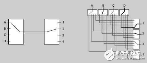
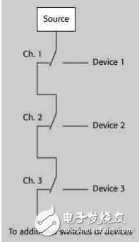
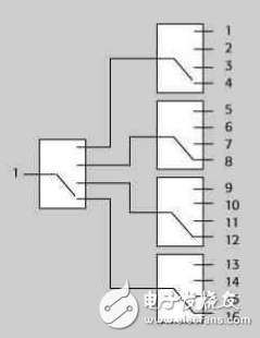
introduction The tremendous growth of the wireless communications industry means that the testing of components and components of wireless devices has ushered in a major explosion, including testing of various RF ICs and microwave monolithic integrated circuits that make up the communication system. These tests usually require very high frequencies and are generally in the GHz range. This article discusses key issues in RF and microwave switching test systems, including different switch types, RF switch card specifications, and issues to consider in RF switch designs that help test engineers improve test throughput and reduce test costs. The difference between RF switch and low frequency switch It seems easy to convert one signal from one frequency point to another, but how do you achieve this with very low signal loss? Switching systems that design low frequency and direct current (DC) signals need to consider their unique parameters, including contact potential, settling time, bias current, and isolation characteristics. High-frequency signals, similar to low-frequency signals, need to consider their unique parameters that affect the signal performance during switching, including VSWR (voltage standing wave ratio), insertion loss, bandwidth, and channel isolation. In addition, hardware factors such as terminations, connector types, and relay types can greatly affect these parameters. Switch type and construction Capacitance within the relay is a common factor limiting the signal frequency of the switch. The material and physical properties of the relay determine the internal capacitance of the relay. such as, In RF and microwave switches over 40 GHz, special contact architectures are used in electromechanical relays for better performance. Figure 1 shows a typical configuration with a common termination between the two switch terminations. All signal connections are coaxial to ensure optimal signal integrity (SI). In this case, the connector is an SMA female. For more complex switch configurations, the common termination is terminated by a respective switch termination in a radial manner. ▲ Figure 1 – High frequency electromechanical relay A series of complex switching topologies are used in RF switches. A matrix switch allows each input to be connected to each output. There are two types of matrices that are used in microwave switch architectures - blocking and non-blocking architectures. A blocking matrix can connect any one input to any one of the outputs, so other inputs and outputs cannot be connected at the same time. This is an effective low-cost solution for applications that only need to switch to one signal frequency at a time, and signal integrity is better because there are fewer relay paths, especially to avoid phase delay problems. The non-blocking matrix allows simultaneous connection of multiple paths. This architecture has more relays and cables, so it is more flexible, but at a higher price. ▲ Figure 2 – Single channel blocking matrix and non-blocking matrix The stacked switch architecture is an alternative to multi-position switches. It uses multiple relays to connect one input to multiple outputs. The path length (which also determines the phase delay) is determined by the number of relays through which the signal passes. ▲ Figure 3 - Cascade Switch Architecture The tree architecture is an alternative to the stacked switch architecture. Compared to the cascading architecture, the tree technology requires more relays for systems of the same size. However, the isolation between the selected path and other unused paths is better, thus reducing the gap between the relay and the channel. Crosstalk. The tree architecture has some advantages, including unterminated stubs, and the characteristics of each channel are similar. However, having multiple relays on a selected path means that the losses are greater and the signal integrity is worrying. ▲ Figure 4 – Multiple switch (illustrated as a double switch) RF switch card architecture In the RF switch card application on the test instrument host, many electrical performance indicators need to be understood to ensure signal integrity. • Crosstalk is the capacitive, inductive, or electromagnetic radiation generated between signals transmitted on different channels or between signals on the channel and the output signal. It is generally described by a specific load impedance and the number of decibels at a particular frequency. • Insertion loss is the attenuation of a signal as it travels through a switch card or system, expressed in decibels over a specific frequency range. Insertion loss is a very important technical indicator when the signal is low or the noise is high. • Voltage standing wave ratio (VSWR) is a measure of the reflection of a signal on a transmission line and is defined as the ratio of the highest voltage amplitude to the lowest voltage amplitude of the standing wave on the signal path. • A limited range of frequencies at which a signal is switched, transmitted, or amplified is referred to as bandwidth. For a given load condition, the bandwidth range is defined by the -3dB (half power) point. • Isolation is the ratio of voltages in adjacent channels, defined as the number of decibels over a range of frequencies. RF switch design To design an RF switching system, an additional set of key factors needs to be considered. Impedance Matching - Assuming that the switch is placed between the measuring instrument and the DUT (device under test), all impedances in several systems must match. For optimal signal transmission, the output impedance of the source should be equal to the characteristic impedance of the switch, the impedance of the cable, and the impedance of the DUT. In RF testing, the common impedance level is 50 or 75 ohms. Regardless of the impedance level required, proper impedance matching will ensure overall system integrity. The input VSWR and the signal path through VSWR determine the accuracy of the measurement. Mismatch Uncertainty(dB) = 20 x log(1 +/- Γsig path * Γinst) Where Γ = VSWR-1/VSWR +1 If the signal path output and instrument input have a good VSWR, such as 1.3:1, the Mismatch Uncertainty is about +/- 0.15 dB. Termination - At high frequencies, all signals must be properly terminated, otherwise electromagnetic waves will be reflected at the termination points, resulting in an increase in VSWR. A switch that is not terminated will increase the VSWR in the off state, and a switch typically needs to provide a 50 ohm terminating resistor to match the connected or disconnected state. After the VSWR is increased, if the reflection portion is large enough, it may even damage the source. Power Transfer - Another important consideration is the ability of the system to transmit RF power from the instrument to the DUT. The signal may need to be amplified due to insertion loss. In some applications, it may be desirable to reduce the power of the signal to the DUT. The use of an amplifier or attenuator ensures that accurate signal power values ​​are transmitted to the switching system. Signal Filters - Signal filters are useful in some situations, such as when noise is accidentally added to a signal transmitted through a switch. Filters are also useful if the original signal frequency is not suitable for the DUT test frequency. In this case, a filter can be added to the switch to change the signal bandwidth or to filter out unwanted signal frequencies. Phase Distortion - As the size of the test system increases, signals coming from the same source may be transmitted to the DUT in different ways, resulting in phase distortion. This indicator is often referred to as the transmission delay. For a given conductive medium, the delay is proportional to the length of the signal path. Different signal path lengths will cause the signal phase to move, resulting in erroneous measurements. To reduce phase distortion, ensure that the signal path length is the same. to sum up Discuss and understand the various design parameters in the RF/microwave switching system purchase and construction to ensure signal and system integrity.
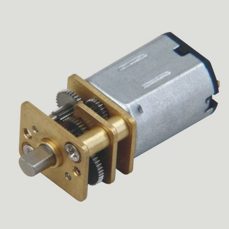
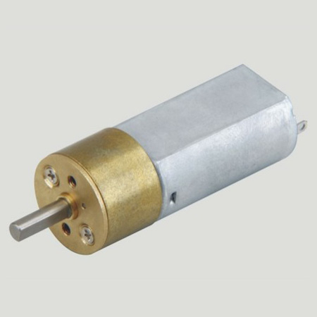
Dc gear motor, namely gear reduction motor, is based on ordinary Dc Motor, coupled with gear reduction gearbox.
The gear reducer is used to provide low speed and large torque.
At the same time, the gearbox with different deceleration ratio can provide different speed and torque.
Generally different industries, using different power dc motor, generally adopt custom parameter design pattern.
What are the four ratings of the Dc Gear Motor? The DC gear motor is often seen in our industrial production. Here Shunchang Motor gives you the knowledge of its four ratings. To talk about
precision instruments and meters,automobile industry, medical equipment, consumer electronics, household appliances, electric glass doors and Windows,etc., wide application range
Features: gear motor drive precision, small volume, large torque, low noise, durability, low energy consumption, customized power design,easy installation, easy maintenance;Simplify design and save space.
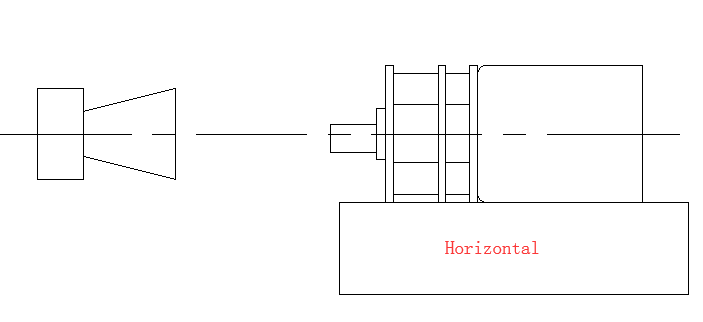
Method of use: the best stable in horizontal plane, installed on the dc gear motor output shaft parts, cannot use a hammer to knock,knock prone to press into the dc gear motor drive, may cause damage to internal components, and cannot be used in the case of blocked.
Operating temperature range:
Geared motors should be used at a temperature of -10~60℃.
The figures stated in the catalog specifications are based on use at ordinary room temperature catalog specifications re based on use at ordinary room temperature (approximately20~25℃.
If a geared motor is used outside the prescribed temperature range,the grease on the gearhead area will become unable to function normally and the motor will become unable to start.Depending on the temperature conditions ,it may be possible to deal with them by changing the grease of the motor's parts.Please feel free to consult with us about this.
Storage temperature range:
Geared motors should be stored ta a temperature of -15~65℃.
In case of storage outside this range,the grease on the gearhead area will become unable to function normally and the motor will become unable to start.
Service life:
â—Use with a load that exceeds the rated torque
â—Frequent starting
â—Momentary reversals of turning direction
â—Impact loads
â—Long-term continuous operation
â—Forced turning using the output shaft
â—Use in which the permitted overhang load or the permitted thrust load is exceeded
â—A pulse drive ,e.g.,a short break,counter electromotive force,PWM control
â—Use of a voltage that is nonstandard as regards the rated voltage
â—Use outside the prescribed temperature or relative-humidity range,or in a special environment.
â—Please consult with us about these or any other conditions of use that may apply,so that we can be sure that you select the most appropriate model.
when it come to volume production,we're a major player as well .each month,we rurn out 600000 units,all of which are compliant with the rohs directive.Have any questions or special needed, please contact us, we have the engineer group and best sales department to service to you Looking forward to your inquiry. Welcome to our factory.
Gear Motor,Micro Gear Motor,Small Gear Motor,Bike Lock Gear Motor Shenzhen Shunchang Motor Co., LTD. , https://www.scgearmotor.com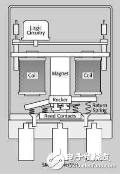
1. Rated Current: The rated current is the maximum current allowed to flow through the armature winding of the DC deceleration motor in accordance with the specified operating mode, in A.
2. Rated Voltage: The rated voltage is the maximum additional voltage that the armature winding of the motor can work safely, unit V. It
3. Rated Speed: Rated speed refers to the rotational speed of the Gear Reducer Motor in the rated voltage, rated current and output rated power under the circumstances of operation, the unit is r/min. Such
4, rated power: rated power refers to the motor in accordance with the specified mode of operation can provide output power. For motor, rated power is the output of mechanical power on the shaft.

