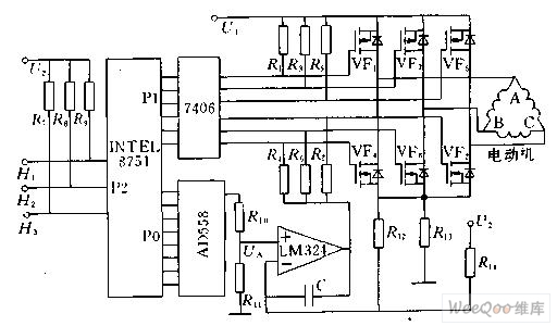
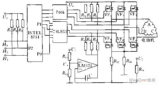
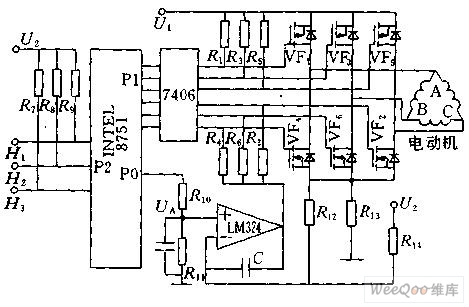
Figure 1 shows the block diagram of the 8751 microcontroller to control the DC brushless motor. The P1 port of the 8751 is connected to the 7406 inverter to control the commutation of the DC brushless motor. The P2 port is used to measure the signals H1, H2 and H3 from the position sensor. The P0 port is connected to a digital-to-analog converter. Figure 1 Schematic diagram of DC brushless motor computer control Commutation control According to the commutation mode of the stator winding, firstly find the state of the three rotor magnet position sensor signals H1, H2, H3, and the relationship between the six power tubes is placed in the EEPROM of the microcontroller in tabular form. According to the state from H1, H2, and H3, the corresponding power tube can be found and sent out through the P1 port to realize the commutation of the DC brushless motor. Starting current limit The resistor R13 is connected in series in the main circuit, so Uf=R13*IM, the magnitude of which is proportional to the current IM of the motor. The output voltage U0 of the Uf and the digital-to-analog converter is respectively sent to the two input terminals of the LM324 operational amplifier. Once the feedback voltage is greater than Uf than the given signal U0 from the digital-to-analog conversion, the LM324 outputs a low level, so that the main loop The three power tubes VF4, VF6, and VF2 cannot be turned on, thereby cutting off all current paths of the stator winding of the DC brushless motor, forcing the motor current to drop. Once the current drops to Uf less than U0, the LM324 output returns to the high level. The main circuit is also capable of conducting, which acts to limit the current. Speed ​​control In the normal operation of the DC brushless motor, the current of the DC brushless motor can be controlled by controlling the output voltage U0 of the digital-to-analog converter, thereby controlling the current of the motor. That is, the 8751 single-chip computer calculates the rotational speed of the motor through the period of the sensor signal, and compares it with the given rotational speed. If it is higher than the given rotational speed, the output value of the P2 port is reduced, the motor current is reduced, and the rotational speed is reduced. . On the contrary, the output value of the P2 port is increased, thereby increasing the rotational speed of the motor. PWM control implementation Speed ​​control can also be achieved by PWM. Figure 2 and Figure 3 show the control of the DC brushless motor speed by PWM control. Figure 2 PWM control schematic Figure 3 PWM control schematic The forward and reverse rotation of the brushless DC motor changes its direction of rotation by changing the commutation order. The specific method only needs to replace the commutation control table. Long wave pass filters are usually used for wavelength order classification. One side is plated with hard medium long wave pass filter film and the other side is plated with antireflection film, which can cut off sharp light at a specific wavelength, while the other wavelength region has high transmission, so as to achieve the purpose of isolating a wide region of the spectrum
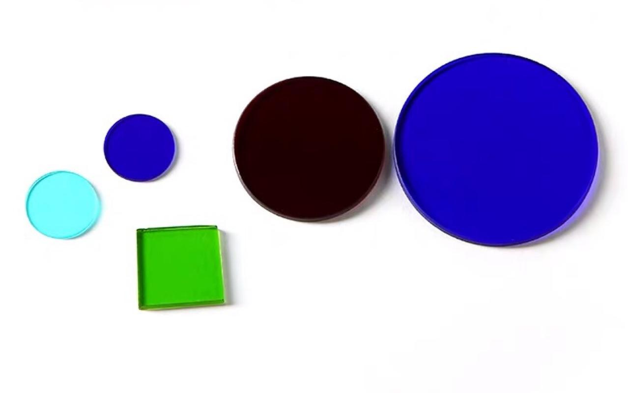
The filter is made of plastic or glass with special dyes. The red filter can only let the red light pass through, and so on. The transmittance of glass sheet is similar to that of air, and all colored light can pass through, so it is transparent. However, after dyeing with dye, the molecular structure changes, the refractive index also changes, and the passage of some colored light changes. For example, when a white light passes through a blue filter, it emits a blue light, while there are very few green and red light, and most of them are absorbed by the filter.
Long Wave-pass Fliter Hanzhong Hengpu Photoelectric Technology Co.,Ltd , https://www.hplenses.com


Filter is an optical device used to select the required radiation band. A common feature of filters is that no filter can make the imaging of celestial bodies brighter, because all filters will absorb certain wavelengths, making objects darker.
