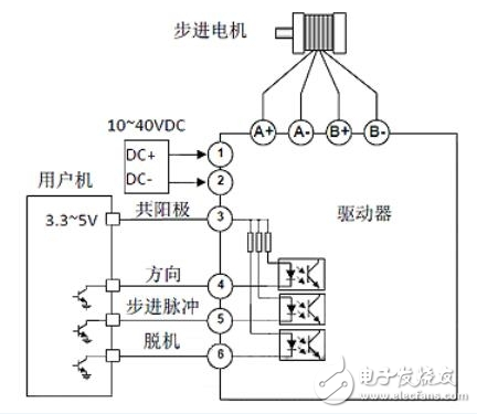
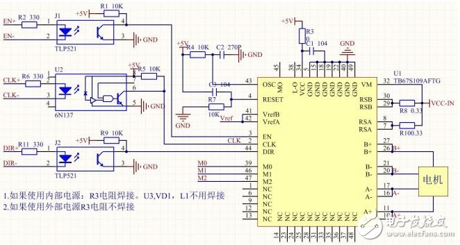
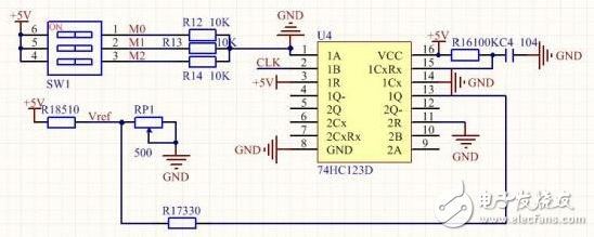
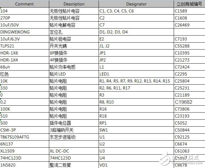
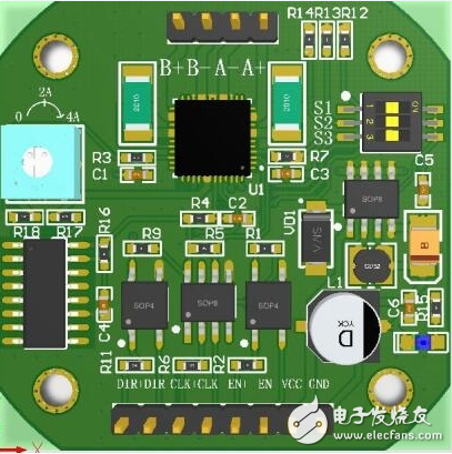
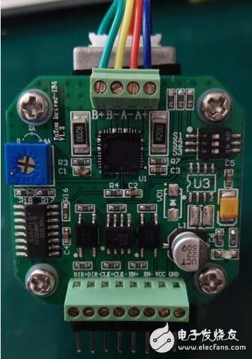
Stepper motor is an open-loop control motor that converts electrical pulse signals into angular displacement or linear displacement. It is the main actuator in modern digital program control systems and is widely used. In the case of non-overload, the speed and stop position of the motor depend only on the frequency of the pulse signal and the number of pulses, and are not affected by the load change. When the stepper driver receives a pulse signal, it drives the stepper motor. The set direction is rotated by a fixed angle called the "step angle" whose rotation is performed step by step at a fixed angle. The angular displacement can be controlled by controlling the number of pulses to achieve the purpose of accurate positioning. At the same time, the speed and acceleration of the motor rotation can be controlled by controlling the pulse frequency, thereby achieving the purpose of speed regulation. The stepping motor is an induction motor. Its working principle is to use electronic circuit to supply power when the DC power is changed into components. The multi-phase timing control current is used to supply the stepping motor with this current, and the stepping motor can work normally. The driver is a time-sharing power supply for the stepper motor, multi-phase timing controller. Although stepper motors have been widely used, stepper motors are not as conventional DC motors, and AC motors are used under normal conditions. It must be composed of a dual ring pulse signal, a power drive circuit, etc. to form a control system. This work mainly uses the TB67S109A motor driver. The TB67S109A is a two-phase bipolar stepper motor driver with a PWM chopper with a built-in clock decoder. Features have the following points: 1, able to control a bipolar stepper motor 2, can use PWM to control constant current drive 3. Allow full step, half step, quarter, 1/8, 1/16, 1/32 steps. 4. Error detection (TSD/ISD) signal output function. 5, built-in error detection circuit (thermal shutdown (TSD), over current shutdown (ISD), and power-on reset (POR) 5. The chopping frequency of the motor can be customized by external resistors and capacitors. Remark: The stepping motor can't be directly connected to the power frequency AC or DC power supply, but a dedicated stepper motor driver must be used. It consists of a pulse generation control unit, a power drive unit, and a protection unit. The drive unit is directly coupled to the stepper motor and can also be understood as the power interface of the stepper motor microcomputer controller. 4.1 TB67S109A drive circuit Remark: Stepper motor driver, which converts the pulse signal from the control system into the angular displacement of the stepper motor, or: the control system sends a pulse signal every time, and the stepper motor rotates by one step angle through the driver. That is to say, the speed of the stepping motor is proportional to the frequency of the pulse signal. Therefore, by controlling the frequency of the stepping pulse signal, the motor can be precisely adjusted; by controlling the number of stepping pulses, the motor can be accurately positioned. 4.2 logic circuit Remark: As shown in the figure above, this is a dual retriggerable monostable multivibrator consisting of 74HC123D. Its function is to automatically reduce the drive current to half when no pulse signal is received. The role of M0, M1, M2 is to select the subdivision. 4.3 Power circuit Remark: Since the MCU works at 5V, and the working voltage of the stepper motor is several tens of V, the XL1509 is required to regulate the power supply to 5V to supply voltage to the MCU. The main component materials. In this electronic production, I found some things that need special attention for stepper motors, which are presented here for your reference: 1. Stepper motor is used in low-speed occasions---the speed per minute does not exceed 1000 rpm, (6666PPS at 0.9 degrees), preferably between 1000-3000PPS (0.9 degrees), which can be used to work here through the reduction gear. At this time, the motor has high working efficiency and low noise; 2. It is better not to use the whole step state of the stepping motor, and the vibration is large in the whole step state; 3. When the motor is at a high speed or a large inertia load, it is generally not started at the working speed, but the speed is increased by gradually increasing the frequency. First, the motor does not lose the step. Second, the noise can be reduced and the positioning accuracy of the stop can be improved; 4, should follow the principle of selecting the motor after the first selection of the motor. Transparent Led Film Screen,Adhesive Transparent Led Display,Adhesive Led Transparent Film Screen,Transparent Led Display Film Screen Guangdong Rayee Optoelectronic Technology Co.,Ltd. , https://www.rayeeled.com

Stepper motor design based on TB67S109A motor driver (graphic)
First, the work profile Seven, summary