Description of sensor functions  Switching on  Normal mode  Procedure for assigning parameters
24HR Electronic Timer socket with photocell.
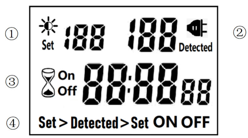
â‘ Light intensity setting
â‘¡ Light intensity detection
â‘¢ Countdown Timer ON & OFF
â‘£ 4 MODES:
Set > Detected: When the light intensity detection value is less than the set value, switch ON or OFF.
Detected > Set: When the light intensity detection value is greater than the set value, switch ON or OFF
ON : Always ON
OFF : Always OFF
NOTED:
1. The light intensity displayed by this machine is not the standard light intensity value (Lux), only the relative light intensity value.
2. The light intensity value is affected by the placement position and direction. Please determine the position first and then set it according to the actual light intensity detected. If you change the position or change the orientation, you need to reset the light intensity setting value suitable for the new position.
3. This product has built-in rechargeable battery. If it is not connected to AC for a long time, you need to connect the power supply to charge until the LCD can display normally.
MANUAL OPERATION
1. Press [UP" or [DOWN" to set the LUX value.
2. Press the [SET" key to start setting, and the P1 settable items will be flashed.
3. Press [UP" or [DOWN" to adjust the value.
4. Press [SET" key again to exit setting or enter next setting for countdown timer.
5. Repeat the [SET" key to start setting, and the P2 & P3 settable items will be flashed.
6. Press the [FUN" key to switch the working state in the following:
Set > Detected -> Detected > Set -> ON -> OFF
Set > Detected: Automatically switches when the detected ambient light intensity is darker than the set value
Detected >Set: Automatically switch when the detected ambient light intensity is brighter than the set value
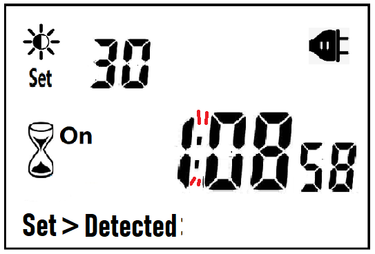
When the brightness meets the setting conditions, the countdown starts as below:
Note:when the countdown is ON, the detected value is not displayed.
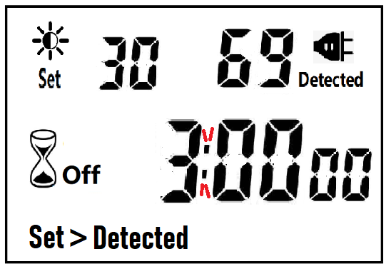
When the brightness does not meet the setting conditions, the countdown stops and waits:
After the countdown ON is reduced to 0, the countdown OFF starts immediately and the power is OFF.
A. If the light intensity meets the set conditions, a new round of countdown will be started;
NOTE:
1. If the power is cut off while the countdown is running, the countdown will be terminated immediately and the relay output will be off. After the power is turned on again, a new round of brightness detection will start.
2. Modifying the brightness value in the countdown operation will not affect the current countdown operation. After the off time of the current countdown, the new brightness setting value will take effect.
3. In the countdown on operation, change the setting value of the countdown on, this countdown will still be timed according to the original setting value; the new setting value will take effect when the next countdown on starts.
Manual Control
Power Detection and Standby Mode
Photocell Timer, photocell timer socket, photocell sensor, photocell sensor socket, sensor plug, sensor switch socket, digital photocell timer, digital sensor timer NINGBO COWELL ELECTRONICS & TECHNOLOGY CO., LTD , https://www.cowellsocket.com
• No TEACH-IN required
• Function indicators visible from all directions
• Insensitive to printing, colors, and shining surfaces
• Material weight from 10 g/m 2 up to over 2000 g/m 2
• Very wide material spectrum, finest papers up to thin sheet metals as well as plastic- and metal foils
• Perpendicular or inclined sensor mounting relative to the sheet plane possible
• Programmable
Technical parameters          Â
General specifications
Sensing range
20 ... 60 mm , optimal distance: 45 mm
Transducer frequency
395 kHz
Indicators/operating means
LED green
indication: single sheet detected
LED yellow
Indication: No sheet detected (Air)
LED red
indication: double sheet detected
Electrical specifications
Operating voltage U b
18 ... 30 V DC , ripple 10 % SS
No-load supply current I 0
< 80 mA
Time delay before availability t v
< 500 ms
Input
Input type
Function input
0-level: -U B ... -U B + 1V
1-level: +U B - 1 V ... +U B
Pulse length
≥ 100 ms
Impedance
≥ 4 kΩ
Output
Output typeÂ
3 switch outputs NPN, NC
Rated operating current I e
3 × 100 mA , short-circuit/overload protected
Voltage drop U d
≤ 2 V
Switch-on delay T on
approx. 15 ms (shorter response time on request)
Switch-off delay T off
approx. 15 ms (shorter response time on request)
Pulse extension
min. 120 ms programmable
Ambient conditions
Ambient temperature
0 ... 60 °C (32 ... 140 °F)
Storage temperature
-40 ... 70 °C (-40 ... 158 °F)
Mechanical specifications
Connection type
cable PVC , 2 m
Core cross-section
0.14 mm
Protection degree
IP67
Material
Housing
nickel plated brass; plastic components: PBT
Transducer
epoxy resin/hollow glass sphere mixture; polyurethane foam
Mass
150 g
General information
Supplementary informationÂ
Switch settings of the external programming adapter:
"output load": pull-up
"output logic": inv
Diagrams           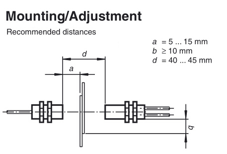
Dimension       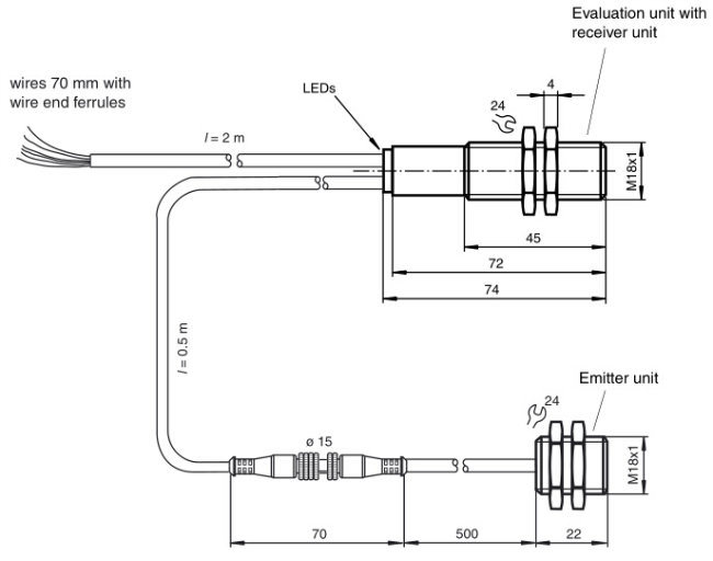
Additional information       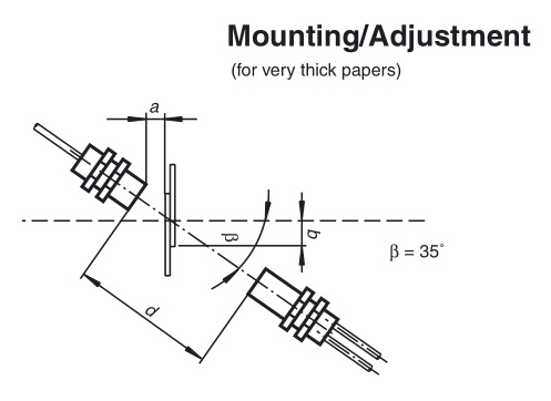
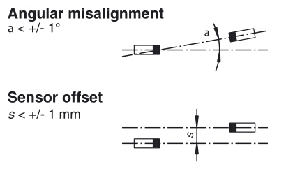
Connection        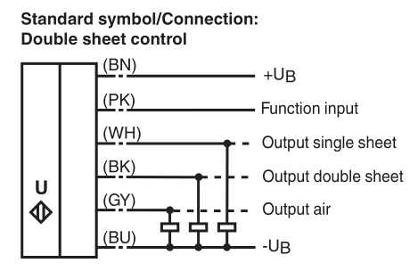
Â
The ultrasonic double sheet monitor is used for double sheet detection in all situations in which the automatic distinction between double and single sheets is required in order to protect machines or avoid waste production. The double-sheet monitor is based on the ultrasonic through-beam principle. The following can be detected:
- No sheet, i.e. air,
- Individual sheet
- Double sheet
A microprocessor system evaluates the signals. The appropriate switch outputs are set as a result of the evaluation. Changes in ambient conditions such as temperature and humidity are compensated for automatically. The interface electronics is integrated into a compact M18 metal housing together with a sensor head.
The sensor is equipped with 6 connections. The functionality of the connections is described in the following table. The function input
(PK) is used to assign parameters to the sensor. (See Output pulse extension, Alignment aid and Program selection). During normal
operation, the function input must always be securely connected with +U B or -U B , to avoid possible interference or improper functionality.
Colour
Switching on
Comments
BN
+U B
Â
WH
Switch output for single sheets
Pulse width corresponds to the event
BK
Switch output for double sheets
Pulse width corresponds to the event
GY
Switch output for air
Pulse width corresponds to the event
PK
-U B /+U B
Function input for parameter assignment/
pulse prolongation
BU
-UB
Â
The sensor is working in normal mode if the function input (PK) is applied to -U B or +U B when the power source (Power-On) is supplied,
as shown in the output pulse extension table (see below).
Displays:
LED yellow:Â Â Â Â Â Detection of air
LED green: Â Â Â Detection of single sheets
LED red: Â Â Â Â Â Detection of double sheets
Switch outputs:
The switch outputs are only active in normal operation!
White:Â Â Â Â Â WHÂ Â Â Â Single sheet output
Black:Â Â Â Â Â BK Â Â Â Double sheet output
Gray:Â Â Â Â Â Â GYÂ Â Â Â Â Â Air output
It is possible to switch to additional parameter assignment modes from the display mode:
        Alignment mode -->
        Program selection mode -->
        Alignment aid mode --> (for checking)
When the function input (PK) is applied to -U B (for > 500 ms), the mode changes. When the "Program selection" mode is active, swit-
ching on function input (PK) on to +U B (for > 500 ms) selects the next program level.
Disconnecting the power supply causes the system to exit the current mode with the selected program change.
The switch outputs are not active while parameters are being assigned to the sensor!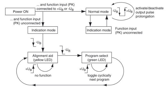
Modes
Amplitude control
During installation, the amplitude control can be used to check whether the ultrasonic amplitude at the receiver is sufficient. If the transmitter is not aligned properly in relation to the receiver, maximum sound energy is not transmitted to the receiver, which may result in the incorrect detection of materials.
When the sensor detects an area of air (yellow LED lights up), the UDC begins to display the strength of the measured amplitude signal:
- if the signal is weak, the yellow LED flashes at low frequency
- the flashing frequency increases in line with the signal strength
- the yellow LED lights up continuously when the signal strength is sufficient.
The single sheet function (green LED) and double sheet function (red LED) are now active. This can be used to check the correct
function of the sensor.
Program selection
In the program selection mode, the current program is displayed by the green LED (number of flashing pulses = program number).
Applying the adjustment input (PK) to +U B (for > 500 ms) causes the next program to be selected in cyclic sequence (program 1 follows through to program 4).


After the countdown OFF is reduced to 0:
B. If the light intensity does not meet the set conditions, keep the power off and wait for the light to meet the conditions before turning on automatically.
4. In the countdown off operation, change the setting value of countdown off, this countdown will still be timed according to the original setting value; the new setting value will take effect when the next countdown off is started.
NOTE: the brightness setting value, countdown ON or countdown OFF, any one of which is equal to 0, cannot be switched ON or OFF automatically.
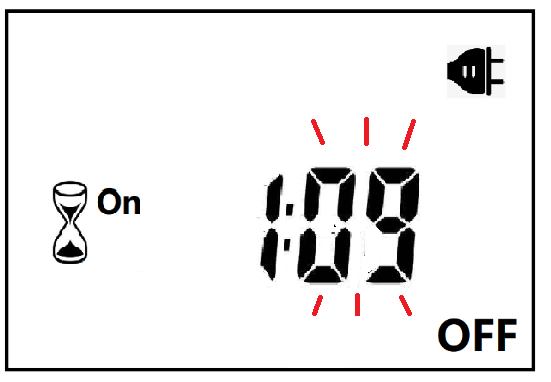
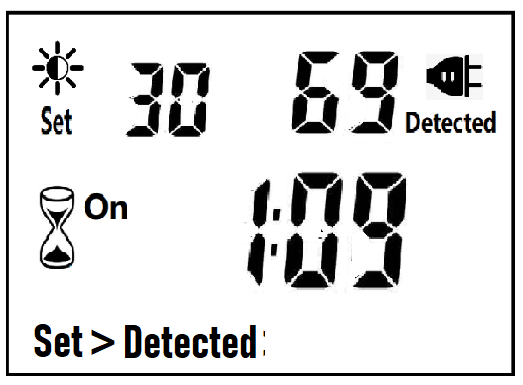
When ON or OFF is displayed, it means that the power supply remains ON or OFF, as shown in the figure below:

With AC power supply, the icon ![]() lights up and works normally.
lights up and works normally.
When there is no AC power supply, the icon ![]() goes out, the brightness is not detected at this time, and the system enters the standby mode.
goes out, the brightness is not detected at this time, and the system enters the standby mode.
Ultrasonic Double Sheet Sensor (UDC-18GM-400-3E1)
Model NO.: UDC-18GM-400-3E1
Customized: Customized
Color: Silver
Usage: Position Sensor
Theory: Ultrasonic Sensor
Material: Plastic
Warranty: 1 Year
Trademark: Winston/OEM/Neutral
Transport Package: Neutral Carton Packing
Specification: CE
Origin: China, Zhejiang, Wenzhou
HS Code: 90330000
• Ultrasonic system for reliable detection of no, one, or two overlapping sheet materials, preferably papers