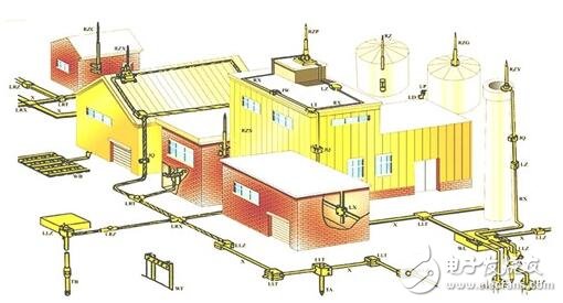
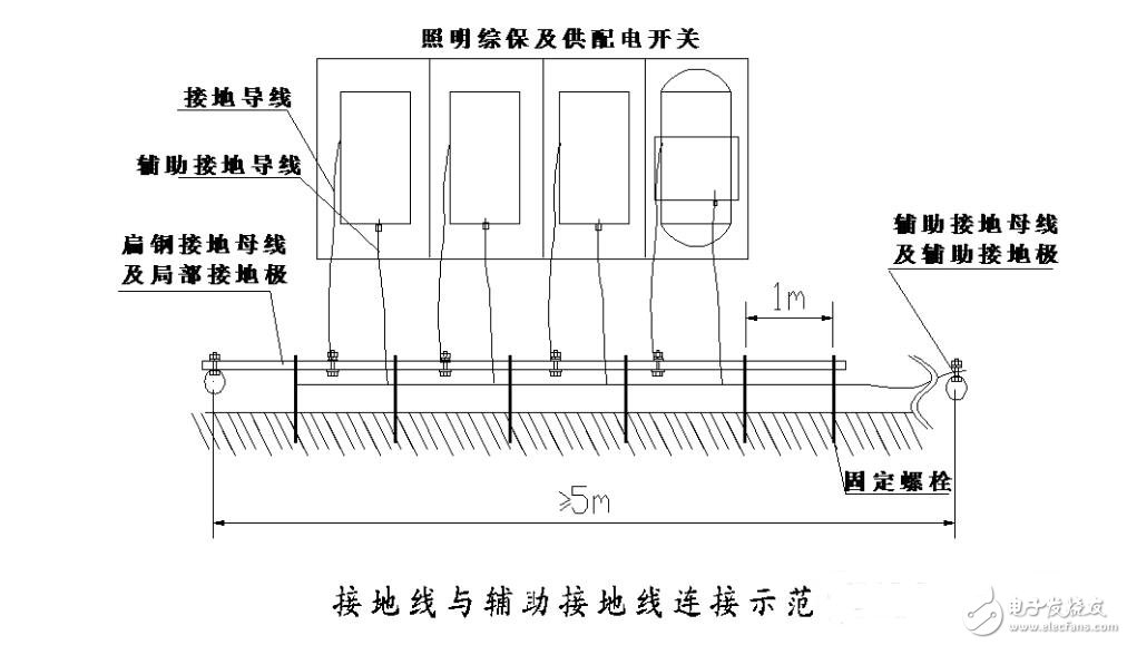
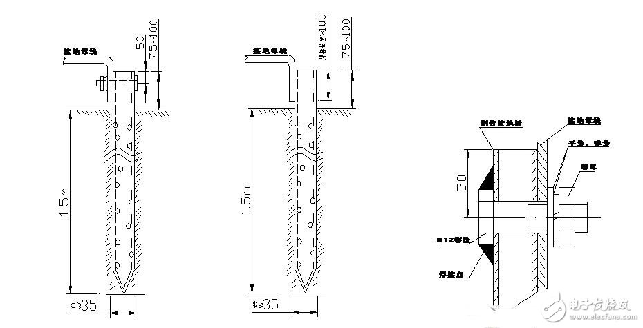
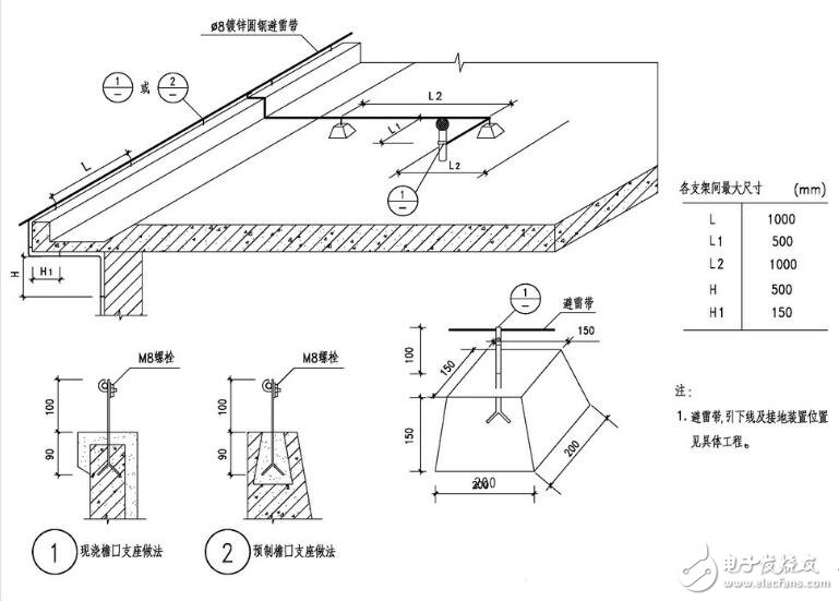
The grounding device is a general term for a grounding electrode buried in the ground and a connecting wire from the grounding electrode to the device. The grounding device is also called a grounding integrated device: a device that electrically connects an electrical device or other object to the ground. A metal object that is in direct contact with the earth to make an electrical connection is a ground electrode. It can be an artificial ground or a natural ground. This grounding pole can be assigned some electrical function, such as for system grounding, protective grounding or signal grounding. The grounding device is composed of a grounding body (round steel, angle steel, flat steel, steel pipe, etc.) embedded in the soil and a grounding wire for connection. First, according to the purpose of grounding, the grounding of electrical equipment can be divided into: working grounding, lightning protection grounding, protective grounding, instrument control grounding. 1. Working grounding: It is the grounding required to ensure the normal operation of the power system. For example, the neutral point of the transformer in the neutral point direct grounding system is used to stabilize the grid to ground potential, thereby reducing the insulation to ground. 2. Lightning protection grounding: It is the grounding set for the needs of lightning protection. For example, lightning rod (wire) (now called lightning rod, wire, belt), lightning arrester grounding, the purpose is to make lightning current smoothly into the earth, in order to help reduce the lightning overvoltage, it is also called overvoltage protection grounding. 3, protective grounding: also known as safety grounding, is the grounding for personal safety, that is, the electrical equipment shell (including cable skin) must be grounded to prevent the shell from being charged and endangering personal safety. 4, instrument control grounding: power plant thermal control system, data acquisition system, computer monitoring system, transistor or micro-type relay protection system and telecontrol communication system, in order to stabilize the potential, prevent interference and set the ground. Also known as electronic system grounding. The basic concept of grounding resistance: Grounding resistance is the resistance encountered when current flows through the grounding body into the ground and spreads around. The earth has a certain resistivity, and if there is a current flowing, the earth has different potentials everywhere. After the current is injected into the earth through the grounding body, it spreads in four places in the form of a current field. The farther away from the grounding point, the larger the hemispherical diffusing area, the smaller the current density in the ground, so it can be considered at a distance ( Outside the 15~20m), the resistance of the unit diffusion distance and the current density in the ground are close to zero, and the potential at this point is zero potential. In the figure, the curve U=f(r) represents the potential distribution of the ground surface (r represents the distance from the lightning current injection point). The ratio of the potential Um at the grounding point to the grounding current I is defined as the grounding resistance R at that point, R = Um / I. When the grounding current is constant, the smaller the grounding resistance, the lower the potential Um, and vice versa. The grounding resistance depends mainly on the structure and size of the grounding device, the depth of the buried ground, and the local soil resistivity. Since the electrical resistivity of the metal grounding body is much smaller than the soil resistivity, the resistance of the grounding body itself is negligible in the grounding resistance. Under normal circumstances, there is no electricity. In case of accidents (including lightning strikes), the equipment casing that may be charged needs to be grounded. In principle, all electrical appliances and all metal structures associated with electrical insulation should be grounded. The grounding resistance is of course as small as possible. According to the different requirements of the equipment, the standard is 4--10 ohms, the maximum is not more than 10 ohms, and 4 ohms or less is better, but it is generally difficult to do. Special site requirements, such as: the resistance of the grounding of a hydropower station with a voltage of 110 kV is 0.5 ohm. The grounding wire is a general term. On the specific grounding line, there are grounding, grounding, and grounding branches. The grounding wire is also a general term for the grounding trunk and the grounding branch; if there is only a grounding device and no grounding branch, the grounding wire is the connecting line between the grounding body and the grounding point of the equipment. According to the number of grounding devices according to the number of grounding devices, they can be divided into the following three forms. (1) Single pole grounding device. The single pole grounding device consists of a grounding device consisting of a grounding body and a grounding wire. One end of the grounding wire is connected to the grounding body, and the other end is connected to the grounding point of the electrical equipment. It is suitable for applications where grounding requirements are not too high and electrical equipment has fewer grounding points. (2) Multi-pole grounding device. The multi-pole grounding device is composed of two or more grounding bodies and a grounding wire, and the grounding bodies are connected by a grounding trunk. The grounding trunk and the grounding point of the electrical equipment are connected by a grounding branch. Multi-pole grounding reliability is large, and the grounding resistance is small. It is suitable for occasions where the grounding requirements are high and the electrical equipment has many grounding points. (3) Grounding network. The grounding network connects multiple grounding bodies with a grounding trunk to form a network. It has the characteristics of reliable grounding and low grounding resistance. It is suitable for the grounding of a large number of electrical equipment, and is mostly used in substations, large workshops and other places. The lightning protection grounding device of the building is composed of three parts: the lightning receptor, the down conductor and the grounding body. The grounding body is roughly divided into an artificial grounding body and a grounding body using a deep foundation. (1) Artificial grounding body: One to several sets of grounding bodies are set up according to the size of the house roof. Each group has one to several galvanized angle steel ∠50 & TImes; 50 & TImes; 5 length 2.5 meters, 3 meters apart into the wet underground soil, top 0.7 m below the natural ground, with galvanized flat steel 40 & TImes; 4 welded joints, covering the backfill, and galvanized steel to lead the ground connection test card box, connected to the down line. (2) Using the deep foundation to make the grounding body: high-rise building, using the pillar steel bar as the down conductor, should be no less than two steel bars, welded with the longitudinal reinforcement of the pile or the steel bar of the raft, and the ground beam between the pile and the pile It must also be welded. Where welding joints, no less than two Φ12, the weld length is not less than 8d.
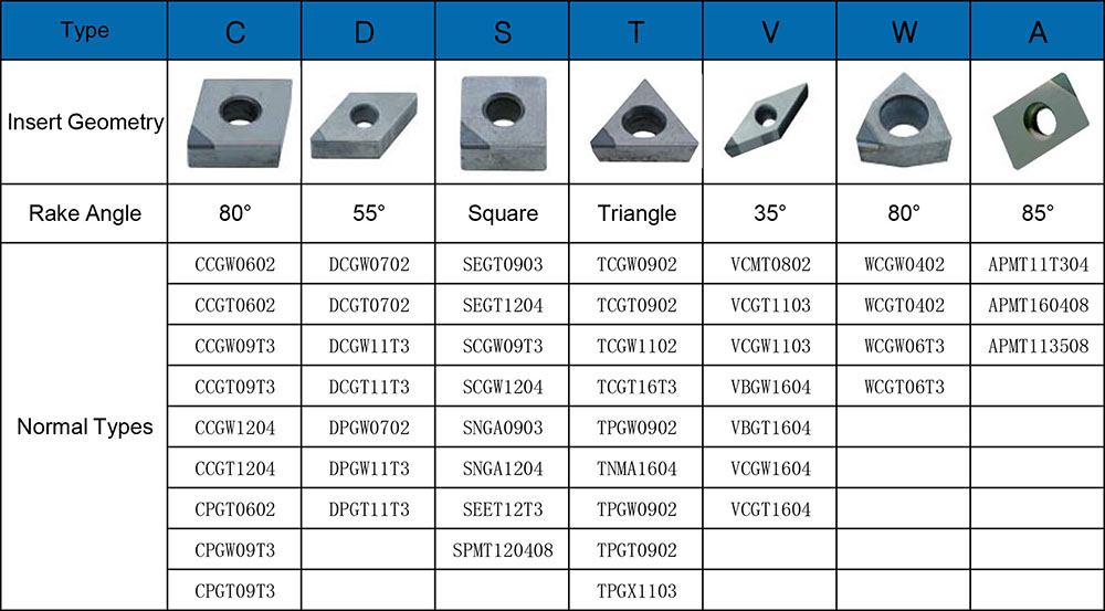
OPT Cutting Tools Co., Ltd specialize in offering a comprehensive gamut of PCD diamond inserts, all of the products are used to machining for cast iron, non-ferrous materials, high-temp alloys, hardend materials.
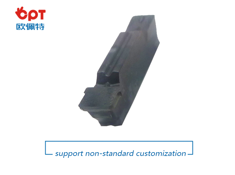
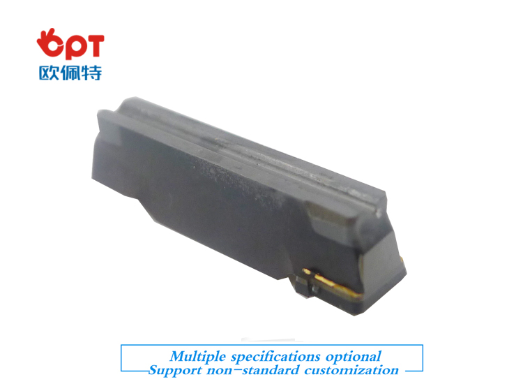
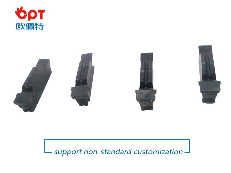
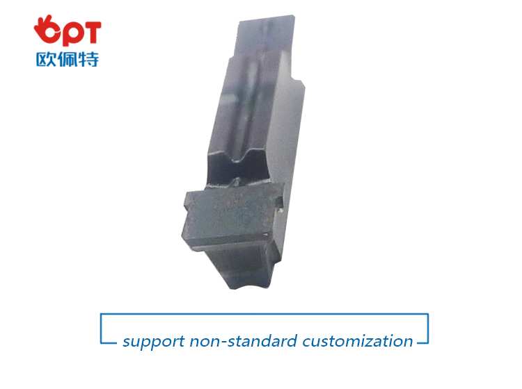
PCD grooving that are to your specific width and depth requirements. We possess the ability to grind special groove, chamfer, and form tools. Tolerances of 2 microns are consistently held on our grooving insert`s geometry and edge preparation.
PRODUCT DETAIL:
product catagory :
PRODUCTING PROGRESS:
PAYMENT AND DELIVERY:
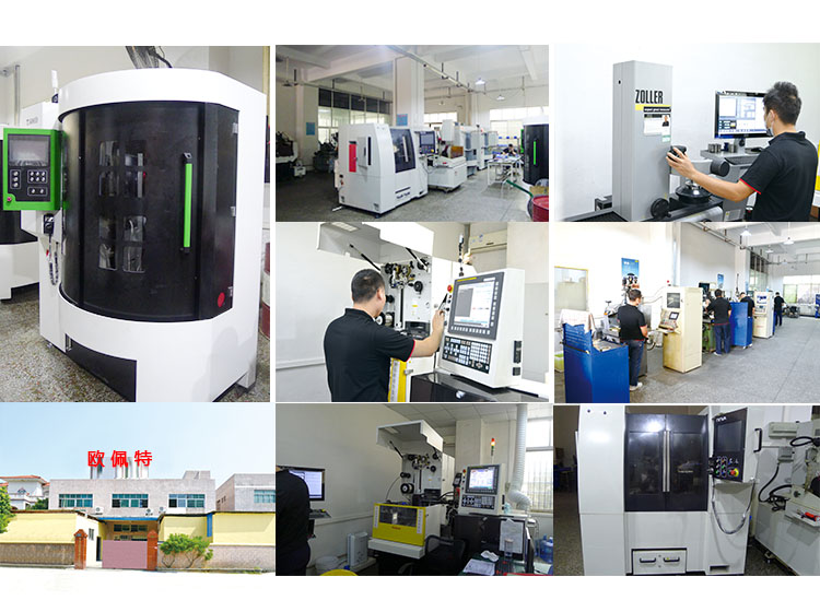
PRODUCT EQUIPMENT :
ABOUT US :
We are specialize in manufacturing PCD diamond tools and Carbide tools. Our major product inclulde PCD Inserts , PCD Reamers , PCD End Mills, PCD Taps, Cabide Inserts,Carbide Drills, Carbide Reams, Taps etc., we also offered customized cutting tools per drawings, and provide package according to customer requirements.
We manufacture a series range of cutting tools for machining of Cast iron, Aluminium alloy and Non-Ferros metal, it is widely used in all major sectors like Automobiles, Engineering, Aerospace, Aviation and 3C industry. Premium quality of raw material is used in the production and strict examination during processing with advanced equipment, so our client are satisfied with our reliable quality and on-time delivery.
Our best selling of cutting tools include PCD Inserts, PCD End Mill, PCD Ball Nose Mill, PCD Reamer, Carbide Taps, Carbide End Mill, Special Form Cutter and many more. For these years we have been made a large forward in the technologies of manufacturing cutting tools. With high quality on performance and price, our product sells well both on domestic and overseas market. And we will always focus on the quality and best service, to make long business relationship.
quanlity control:
We have dedicated team of quality control and precise equipment to keep good and stable performance for our products and processing services.
Grooving Inserts,Grooving Tools,PCD Grooving Tools,PCD Grooving Inserts OPT Cutting Tools Co., Ltd. , https://www.optdiamondtoolss.com