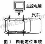
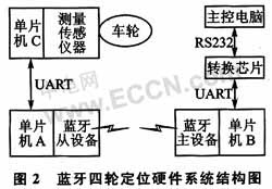
introduction In recent years, with the rapid development of China's automobile industry and the substantial increase in car ownership, automobile inspection technology has also made great progress. The functions and quality of automobile inspection equipment are constantly improving, and it is gradually becoming digital, intelligent and portable. The direction of development. As a basic device for vehicle detection, the four-wheel aligner is a device specifically designed to measure wheel alignment parameters. The four-wheel aligners commonly found in the domestic market are mainly cable-type and wireless-measuring wired transmission. The future development trend is full wireless. How to transform existing wired data transmission systems with low-cost wireless transmission technology has become a very interesting problem in engineering. In this paper, a low-cost wireless transmission Bluetooth technology is proposed, which proposes a scheme to transform the existing four-wheel alignment system of the automobile, and details the software and hardware design method of the wireless vehicle four-wheel alignment system. 1 Traditional design issues and solutions 1.1 Problems with traditional design When the car is shipped from the factory, the positioning angle of its suspension system is set, but the positioning angle will change after the vehicle is running for a period of time. The positioning system is a master computer and four sensors mounted on four wheels. During the test, the four-wheel aligner measures the current four-wheel positioning parameters of the car and transmits the data back to the main control computer; the main control computer will display a list of data measured by the car, and compare with the original data to calculate the deviation value. Then make appropriate adjustments to the parts related to the car. The traditional car wheel aligner relies on wired communication with the host computer and has many limitations. Four-wheel aligners are expensive, domestically produced are generally more than ten thousand yuan, and imported ones are more expensive, generally more than 200,000 yuan. Therefore, in order to wirelessize it, the best solution is to retain the original hardware system and only add the hardware and software of the wireless transceiver unit to avoid secondary investment in the vehicle maintenance station. 1.2 Wireless Solutions Industrial applications often require wireless transmission of data. For example, ultra-high temperature furnaces for drawing crystals during fiber manufacturing require temperature data to be transmitted. The Bluetooth module is small in size, free from obstacles and angles, and relatively inexpensive, and is suitable. In addition to some dedicated Bluetooth modules, most of the Bluetooth module hardware provides a data interface, through the RS232 serial port can transmit real-time data with low speed requirements. This paper chooses Bluetooth technology to design a wireless traditional four-wheel alignment system. Bluetooth works in the free ISM band, and the transmission power is relatively small (generally 1 to 10 mW). It does not cause radio interference to other electrical equipment in the car repair station, and is very suitable for automotive maintenance applications. Bluetooth adopts a point-to-point or point-to-multipoint master-slave network solution, and the Bluetooth four-wheel positioning network adopts a scheme of one master device and four slave devices, as shown in FIG. 1 . This is because modern cars are generally independent of front and rear suspension, so the parameters of the front and rear wheels need to be adjusted independently, can not adopt a point-to-point solution of one master and one slave, but use a master-slave scheme. 2.1 Overall hardware design The Bluetooth master device is a master computer with wireless transceiver function. It is responsible for querying the status of the four wheels and sending adjustment commands to the four wheels. The Bluetooth slave device is four measuring sensors mounted on the wheels of the car and is responsible for measuring four wheels. The status parameter and the measured parameters are wirelessly transmitted back to the host computer. The main control computer stores the standard data of the model. It wirelessly receives the data transmitted from the four wheels (that is, the current four-wheel positioning parameters of the car), and calculates the deviation from the stored value of the vehicle, and makes corresponding judgments. The adjustment command is sent wirelessly to the four wheels. According to this requirement, the hardware system structure is shown in Figure 2. The single chip C and the measuring sensing instrument in Fig. 2 belong to the conventional automobile four wheel aligner before the wireless. The measuring instrument measures the angle of the car wheel and the like, and sends it to the single chip C through the sensor. The process of returning the state parameters of the four wheels back to the main control computer is as follows: the data of the wheel sensor is obtained by the single chip C, and transmitted to the single chip A through the UART port; the single chip A wirelessly transmits the data from the device to the bluetooth main device of the main control computer through the Bluetooth; the single chip B After obtaining the data from the Bluetooth master device, it is converted into a standard RS232 serial port form by the conversion chip, and then sent to the host computer through the standard 9-pin serial port on the PC. The flow of the main control computer sending adjustment commands to the four rounds is similar. In this way, it is convenient to automate the car repair company by simply attaching some components to the conventional four-wheel positioning system. 2.3 Bluetooth module and microcontroller interface circuit design The Bluetooth module uses CSR's Bluecore series CSR0312. The main technical specifications are as follows: â—†The RF output is class2 and the working distance is 10 m. â—†Bluetooth 1.1 certification; â—†FCC&ETST certification; â—† Support UART interface. The MCU is used to store the instruction code for initializing the Bluetooth module and establishing the wireless ACL data connection. It can be said that the software in the MCU is the core of the system. The AT89S51 is used here, and the price of this single chip microcomputer is relatively low. The conversion chip uses the MAX3232E. The circuit connection of the transfer instruction is shown in Figure 3. The UART interface of the Bluetooth module acts as a data transceiving interface RXD and TXD, and communicates with P3.0 and P3.1 of the AT89S51. The AT89S51 transmits data to and from each other through the two interfaces and the Bluetooth module CSR0312, and sends host control interface instructions to it. The P1.2 and P1.3 of the AT89S51 act as an extended serial interface and communicate with other microcontrollers; P3.2 acts as an external interrupt entry. When data is transmitted from other microcontrollers, it will trigger an interrupt to start receiving data. The Bluetooth module communicates with the MCU through the host control interface HCI, and uses the host control interface command. The Bluetooth module can enter a given operation mode (such as querying other devices in the network or establishing a data connection). In this way, the Bluetooth module can be controlled by the single chip microcomputer to realize wireless data transmission. The Bluetooth commands for establishing an ACL connection and disconnecting are: MOV DPTR, #HCICreateACLConnecTIon After receiving the #HCICreateACLConnecTIon signal, the Bluetooth module enters the mode of establishing an ACL connection. The software flow of the master device and the slave device are basically the same. The difference is that the master device needs to query the slave device and establish an ACL data link, and the slave device does not have this part of work. The program flow of the main device is shown in Figure 4. After the system is started, the master device first queries the slave device, and after receiving the response from the slave device, it can be known whether the Bluetooth network can be established with the slave device, and it is determined which one of the four tires the Bluetooth slave device represents; The device initiates a connection request, establishes a wireless ACL link, prepares to send and receive data, and uses an external interrupt to notify that data has arrived. After the four-wheel positioning is completed, the main control computer sends an end signal, and the Bluetooth module connected thereto interprets the signal as disconnecting the Bluetooth connection, notifying the slave device to cancel the Bluetooth network, and the process ends. 4 Summary Although the range of the Bluetooth module is not large, it usually does not exceed 10 m, but it is acceptable for four-wheel positioning. If necessary, the effective distance can also be increased by increasing the transmission power. In general, the Bluetooth module has low cost and flexible networking; compared with the wired four-wheel positioning system, the price has not been greatly improved, and the flexibility of use has been greatly increased. The test results show that the application of Bluetooth technology to the four-wheel aligner not only improves the system stability and work efficiency, but also facilitates the use of the equipment, and can be well adapted to the harsh environment of the vehicle maintenance site. best dc current sensor,best current sensor,ac current sensor,battery current sensor Shanghai Zhilong Electronic Technology Co.,Ltd , https://www.zhilongsensor.com
2 system hardware design 
2.2 Hardware Workflow
â—† Compliance with the Bluetooth 1.1 specification; 
3 system software design
......
MOV DPTR, #HCIDisConnect
...... 