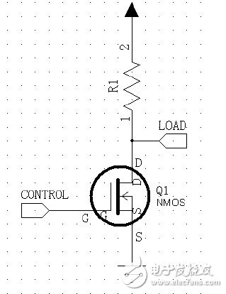
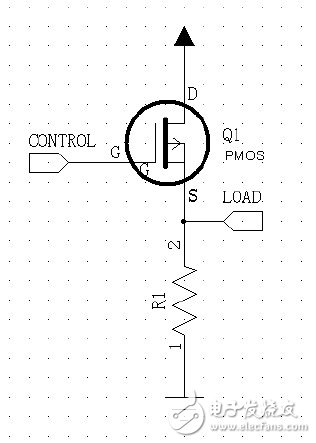
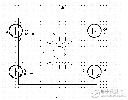
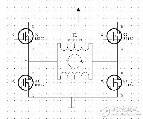
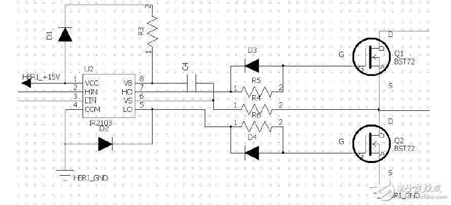
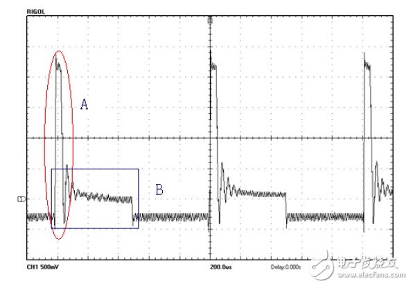
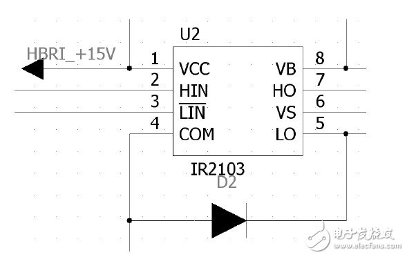
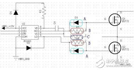
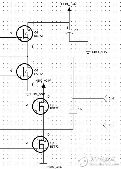
The DC motor has excellent speed regulation characteristics, smooth and convenient speed regulation, wide speed regulation range, strong overload capability, and can realize frequent stepless rapid start, brake and reverse rotation, which can meet various different automation systems in the production process. Special operating requirements, so in the field of industrial control, DC motors have been widely used. Many semiconductor companies have introduced DC-specific driver chips, but most of these chips are only suitable for low-power DC motors. For high-power DC motors, integrated chips are expensive. Based on this, this paper analyzes and discusses various problems that may occur in the design of drive circuit of large power DC motor in detail, and designs and implements a DC motor drive circuit based on 25D60-24A. The circuit has high driving power, strong anti-interference ability and wide application prospects. In the DC motor, the GTR collector output type and the emitter output drive circuit can be used to drive the motor, but they are all non-reversible speed control, the current can not be reversed, no braking ability, and can not be reverse driven, the motor This drive can only be rotated in one direction, so this drive circuit is greatly limited. For inverter speed control, the H-bridge complementary symmetrical drive circuit is the most widely used. The reversible drive allows the current to be reversed, and the four-quadrant operation of the DC motor can be realized, and the positive and negative control of the motor can be effectively realized. There are three main types of motor speed control, adjusting the armature voltage, weakening the excitation flux, and changing the armature loop resistance. Each of the three methods has advantages and disadvantages. Changing the armature loop resistance can only achieve step-level speed regulation. Although the flux can be reduced to achieve smooth speed regulation, the speed range of this method is not large, and generally it is matched with variable voltage speed regulation. use. Therefore, in the DC speed control system, the variable voltage speed regulation is mainly used, and the armature voltage is changed by the PWM (Pulse Width Modulation) signal duty ratio adjustment, thereby achieving smooth motor speed regulation. To control the forward and reverse of the motor, it is necessary to provide the motor with a forward and reverse voltage. This requires a four-way switch to control the voltage at the two inputs of the motor. When the switches S1 and S4 are closed, the current flows from the left end of the motor to the right end of the motor, and the motor rotates in one direction; when the switches S2 and S3 are closed, the current flows from the right end of the motor to the left end of the motor, and the motor rotates in the other direction, the principle of the H-bridge drive The equivalent circuit diagram is shown in Figure 1. Figure 1 H bridge drive principle circuit diagram Commonly used electronic switching devices are relays, transistors, MOS tubes, IGBTs, etc. Ordinary relays are mechanical devices, the number of switches is limited, and the switching speed is relatively slow. Moreover, the inside of the relay is an inductive load, and the interference to the circuit is relatively large. However, the relay can separate the control part from the controlled part, so that a large signal can be controlled by a small signal, and a relay is often used in high voltage control. The triode is a current-driven device. The base current is IB, the collector current is IC, and the amplification factor of the triode is β. If IB*βâ€=IC, the triode is saturated and can be used as a switch. To make the triode in the on state, IB = IC / β, the current of the triode drive tube is proportional to the current at the output of the triode. If the current at the output of the triode is relatively large, the requirements for the drive end of the triode are relatively high. The MOS transistor is a voltage-driven device. For the NMOS, the saturation of the NMOS can be achieved as long as the gate voltage is higher than the source voltage. The energy loss between the turn-on and turn-off of the MOS transistor is only between the gate and the source. The charge and discharge of the parasitic capacitance is not high for the MOS tube drive end. At the same time, the MOS terminal can achieve a large current output, so it is generally used in places where a large current is required. The IGBT is a device that combines the advantages of a triode and a MOS transistor, and is generally used in cases of more than 200V. In this design, the motor operating current is 3.8A, the working voltage is 24V, the motor drive control terminal is 51 series single-chip microcomputer, and the maximum sinking current is 30mA. Therefore, the MOS tube is used as the switching device of the H-bridge. The MOS tube is divided into NMOS and PMOS. The manufacturing process of the two types of tubes is different, and the control methods are different. The NMOS turn-on requires that the gate voltage be greater than the source voltage (10V-15V), while the PMOS turn-on requires that the gate voltage be less than the source voltage (10V-15V). In this design, the 24V single-supply power supply, the NMOS tube on-off control wiring is shown in Figure 2. As long as the G-pole voltage is in the range of 10-15V, the NMOS can be saturated and turned on, and the G-pole voltage is 0. When the NMOS transistor is turned off. Figure 2 NMOS wiring diagram When the on-off control is implemented by the PMOS transistor, the wiring is as shown in Fig. 3. When the G-pole voltage is equal to the power supply voltage VCC, the PMOS is turned off. Figure 3 PMOS wiring diagram 10V "VCC-Vg" 15 PMOS on. When VCC is 15V, the G voltage is VCC-15V when the PMOS is turned on. The PMOS is turned on and off, switching between the power supply voltages VCC and VCC-15V, and the control is not controlled when the power supply voltage VCC is large. Convenience. Comparing Figure 2 and Figure 3, the NMOS is located below the load, and the PMOS is above the load. Replace the switch in Figure 1 with NMOS and PMOS to form an H-bridge composed of MOS transistors, as shown in Figure 4. Figure 4 H-bridge composed of PMOS and NMOS transistors Q1 and Q4 are turned on, the motor rotates in one direction, and Q2 and Q3 turn on the motor in the other direction. In this system, the working voltage of the motor is 24V, that is, the power supply voltage is 24V, then the voltage of the upper tube (PMOS) of the H-bridge to be turned on and off is 24V-15V=9V and 24V, respectively, for the lower tube (NMOS), the turn-on and turn-off voltages are 15V and 0V, respectively. To open and close the upper and lower tubes at the same time, the control circuit used is more complicated. Moreover, the PMOS made by the same process is smaller than the operating current of the NMOS, and the cost of the PMOS is high. The upper and lower tubes are made of PMOS and NMOS, respectively, and the symmetry of the circuit is not good. Due to the above problems, only the NMOS is used as the power switching device when constructing the H-bridge. The H bridge built with NMOS is shown in Figure 5: Figure 5 H-bridge composed of NMOS transistors In the H-bridge composed of the NMOS transistor, the path composed of Q1 and Q4 is first analyzed. When Q1 and Q4 are turned off, the potential at point A is in the “suspended†state (what is the uncertainty potential) (Q2 and Q3 are also turned off). ). Before turning on Q4, first open Q1, and give the voltage of 15V of G1 of Q1. Because point A is “suspended†state, point A can be any level, which may cause Q1 to open failed; after opening Q4, try to open Q1 Before Q1 is turned on, point A is low, and 15V is applied to the G pole of Q1. Q1 is turned on. Since Q1 is saturated, the level of point A is equal to the power supply voltage (the power supply voltage in this system is 24V). When Q1's G-pole voltage is less than Q1's S-pole voltage, Q1 turns off and Q1 turns on. The case of Q2 and Q3 is similar to Q1 and Q4. To open the upper tube of the H-bridge consisting of NMOS, the problem of "suspension" of point A (that is, the S-pole of the upper tube) must be handled. Since the S pole of the NMOS is generally grounded, it is called "floating". To turn on the upper NMOS, the G-pole of the upper tube must have a voltage difference of 10-15V with respect to the floating ground. This requires a boost circuit. In the drive of the H-bridge, in addition to considering the boost circuit of the upper tube, it is also considered that the upper and lower tubes of the same arm of the H-bridge (such as Q1 and Q3 in Fig. 5) cannot be simultaneously turned on. If the upper and lower tubes are turned on at the same time, it is equivalent to short-circuiting from the power supply to the ground, which may burn the MOS tube or the power supply. Even a short-circuit short-circuit phenomenon may cause the MOS to generate heat. A method of inserting a "dead zone" in two state transitions is generally employed in power control to prevent transient short circuits. It is best to satisfy the above two logic conditions when selecting the H-bridge controller, and drive the NMOS with a sufficiently large drive current. In this system, IR2103 is used as the NMOS controller. The IR2103 integrates the boost circuit. The bootstrap capacitor can be completed by only one bootstrap capacitor and one bootstrap diode. The IR2103 integrates a dead-band riser that inserts a “dead zone†during each state transition, while ensuring that the upper and lower tubes are in opposite states. The H-bridge half-bridge circuit consisting of IR2103 and NMOS is shown in Figure 6 below: Figure 6 H bridge half bridge circuit composed of IR2103 and NMOS transistors The selection of the bootstrap capacitor is known from the IR2103 application note depending on several factors: 1. Requires enhanced gate voltage for MGT, 2. IQBS for high-side driver circuits – quiescent current, 3. Internal current of level shifter 4. MGT-gate-source forward leakage current, 5. Bootstrap capacitor leakage current. Factor 5 is only relevant when the bootstrap capacitor is an electrolytic capacitor. If other types of capacitors are used, they can be ignored. The minimum bootstrap capacitance value can be calculated by the following formula (1): Where: Qg = gate charge of the high-side FET, f = operating frequency, ICbs (leak) = bootstrap capacitor leakage current, Iqbs (max) = maximum VBS quiescent current, VCC = voltage source for the logic section, Vf = bootstrap diode Forward voltage drop, VLS = voltage drop across the low-side FET or load, VMin = minimum voltage between VB and VS, Qls = charge required for level shifting per cycle (for 500V/600V MGD) , usually 5nC, and 1200 V MGD is 20 nC. In the figure, D1 is the bootstrap diode and C4 is the bootstrap capacitor. The larger the value of the capacitor, the better. The value of the capacitor is closely related to the operating frequency of the IR2103. The larger the value of the capacitor, the lower the operating frequency. The leakage current of the capacitor has a great influence on the performance of the system. The bootstrap diode has to withstand all the voltages of the system. The forward voltage drop of the bootstrap diode also affects the choice of the bootstrap capacitor. At the same time, the switching speed of the bootstrap diode also directly affects the operating frequency of the system. Ultrafast recovery diodes are generally used. The boost waveform of the bootstrap circuit obtained by the oscilloscope is shown in Figure 7 below: Figure 7 bootstrap circuit boost waveform In the figure, part B is the voltage at the VB terminal after the bootstrap boost. In the figure, part A is because during the process of turning off the upper tube, due to the parasitic diode in the lower tube, the subsequent flow will be generated, causing the VS terminal to generate a negative voltage. Overcharge the capacitor. To reduce the overcharge of the capacitor, a bootstrap capacitor of 0.47uF or more can be used, and a freewheeling diode can be added to the ground and the VS terminal. As shown below: Figure 8 adds a freewheeling diode circuit to the IR2103. In the figure, D2 is a freewheeling diode, and the freewheeling diode can be a common diode. However, the faster the VS voltage is restored, the less obvious the bootstrap capacitor overcharge phenomenon. The system uses 1N4148 as a freewheeling diode. Due to the inductance between the driver and the gate of the MOSFET, the lead of the ground loop, etc., and the parasitic inductance inside the IC and the FET, ringing occurs at the gate of the MOSFET when turned on, which increases the switching loss of the MOSFET. At the same time, EMC is not well controlled. Connect a resistor in series between the gate of the MOSFET and the output of the driver IC (shown as B in Figure 9). This resistor is called “gate resistor†and its function is to adjust the switching speed of the MOSFET, reduce the ringing phenomenon at the gate, reduce EMI, and also limit the current of the gate capacitor. The introduction of this resistor slows down the switching speed of the MOS transistor, but it reduces EMI and stabilizes the gate. Figure 9 Eliminates the ringing circuit. The turn-off time of the MOS transistor is slower than the turn-on time (turning on the charge, turning off the discharge), so it is necessary to change the turn-off speed of the MOS transistor. A diode can be connected in parallel with the gate resistor (see A in Figure 9). When the MOS transistor is turned off, the diode is turned on, shorting the gate resistor to reduce the discharge time. Since a negative voltage may appear on the VS terminal, a suitable resistor can be connected in series at the VS terminal to limit current when generating a negative voltage. For the load motor, it is an inductive device, and at the output of the H-bridge, a small capacitor, and It is necessary to add a decoupling capacitor to the local power supply section. Its circuit is shown below: Figure 10 Current limiting decoupling circuit. In the figure, C7 is a partial decoupling capacitor, which can take 100uF, and C6 is the output capacitor, which is based on the load. Due to the capacitive bootstrap circuit, the capacitor will discharge itself during operation, so the duty cycle of the PWM wave is close to 100% but not 100%. But this does not affect the normal operation of the motor, because of the inherent characteristics of the motor itself. The motor has a small saturation zone, ie the duty cycle is increased and the speed is not significantly changed. Therefore, the above circuit fully meets the needs of the work. In order to test the performance of the drive, the 25D60-24V DC motor is used for closed-loop control. The rated power of the motor is 60W, the rated speed is 2800rpm, the rated voltage is 24V, and the rated current is 3.8A. The maximum speed of the motor can reach 2910rpm. The minimum starting speed of the motor is 44 rpm, and there is no obvious heat generation during the stalling. In order to test the stability of the circuit operation, the motor works for more than 8 hours in three consecutive days, and the heat of the circuit is small; in order to test the circuit's impact resistance and anti-interference ability, the system continuously switches between on and off continuously, and the circuit works. Any failures occur; in addition, the system will work properly with a sudden increase in load. Therefore, it fully satisfies the needs of the drive, and in the design process, in order to prevent the sudden increase of the starting and braking current, the circuit has a large current redundancy, and the highest current in the circuit can reach 8A, effectively ensuring the stability of the circuit operation. And has a strong anti-interference ability. In this paper, a large-power DC motor drive circuit is designed and implemented. From the selection of the device to the realization of the system, various problems that may occur in the circuit design process are analyzed and discussed in detail, and the above problems are solved through theoretical calculation and engineering practice. . The circuit is robust and has a wide range of practicalities, and is particularly suitable for driving DC motors with higher power. 3.6V Cylindrical Battery,3.6V 600Mah Ni-Cd Battery,3.6V 800Mah Ni-Mh Battery,Ni-Mh Battery 3.6V 800Mah Langrui Energy (Shenzhen) Co.,Ltd , https://www.langruibattery.com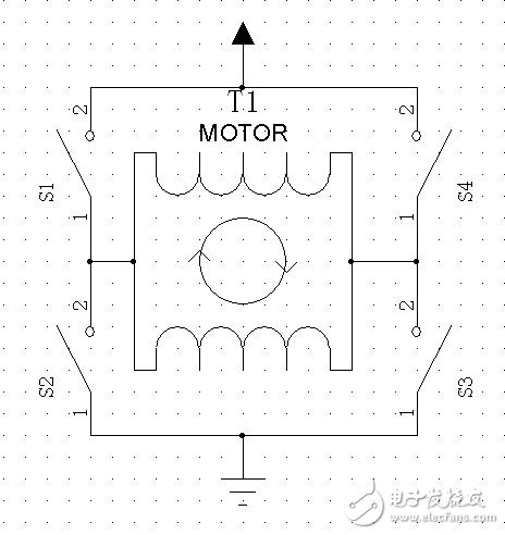

Model
Nominal Voltage
Nominal Capacity
Nominal impedance
Dimension
Charge-discharge standard
Approx Weight
(V)
(mAh)
(mQ)
Diameter
Height
Charge
Discharge
≈g
ICR10220
3.7
130
<150
10
22
0.5C-1C
0.5C-1C
4.1
ICR10440
3.7
350
<120
10
44
0.5C-1C
0.5C-1C
9
ICR14430
3.7
650
<100
13.8
42.8
0.5C-1C
0.5C-1C
17
ICR14500
3.7
900
<80
14
50
0.5C-1C
0.5C-1C
19.5
ICR17280
3.7
600
<100
16.3
28
0.5C-1C
0.5C-1C
15
ICR17335
3.7
700
<100
16.3
33.5
0.5C-1C
0.5C-1C
18
ICR18500
3.7
1400
<70
18.1
50
0.5C-1C
0.5C-1C
33
ICR18650
3.7
2000
<50
18.1
64.8
0.5C-1C
0.5C-1C
45
ICR18650P
3.7
2000
<40
18.1
65
0.5C-1C
3C-5C
45
ICR18650P
3.7
2200
<40
18.1
65
0.5C-1C
3C-5C
45
ICR18650
3.7
2600
<70
18.1
64.8
0.5C-1C
0.5C-1C
45
ICR26650
3.7
3500
<30
26
65.5
0.5C-1C
0.5C-1C
85
ICR26650P
3.7
5000
<30
26
65.5
0.5C-1C
0.5C-1C
85
ICR18650P
3.7
1500
<15
18.1
64.8
1C
10C-15C
47
ICR26650P
3.7
2200
<15
26
64.8
1C
10C-15C
64
IFR14430E
3.2
400
<115
13.8
43
0.5C-1C
0.5C-1C
15
IFR14500E
3.2
400
<95
13.8
50.2
0.5C-1C
0.5C-1C
15.5
IFR14500E
3.2
650
<80
13.8
50.2
0.5C-1C
0.5C-1C
17.8
IFR18500E
3.2
600
<80
18
50
0.5C-1C
0.5C-1C
19.5
IFR18500E
3.2
1200
<80
18
64.8
0.5C-1C
0.5C-1C
30.4
IFR18650E
3.2
1500
<65
18
64.8
0.5C-1C
0.5C-1C
40.5
IFR18650E
3.2
1700
<80
18
65.3
0.5C-1C
0.5C-1C
41.2
IFR26650E
3.2
3400
<20
26
65.3
0.5C-1C
0.5C-1C
87
IFR18650P
3.2
1100
<20
18
65.3
1-3C
10-25C
40
IFR26650P
3.2
2400
<20
26
65.3
1-3C
10-25C
82
Design and implement a DC motor with higher power based on the drive and control principle of DC motor H-bridge
1 Introduction