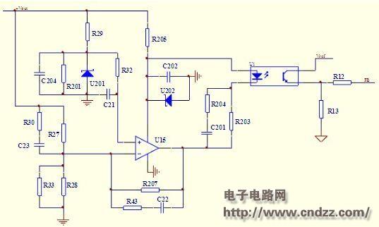
Overview: 1 Circuit type, main function description The circuit shown in the figure below belongs to the voltage feedback circuit. When the output voltage changes, the feedback circuit feeds back to the control chip to adjust the output voltage and stabilize the output voltage. The circuit is as follows: 1.2 Working principle analysis When the output voltage changes, the voltage is inverted by R27 and R28, and the voltage of the inverting input terminal of U15 changes. By comparing with the fixed voltage of the non-inverting input terminal of U15, the output voltage is amplified by the op amp, and the optocoupler is passed through the optocoupler. The current change at the LED end is transmitted to the output of the three-stage tube of the optocoupler, and then input to the control chip, and the control chip adjusts the output voltage to achieve stable output voltage. 2 uc3842 Introduction Figure 1 shows the internal structure of the UC3842PWM controller. The internal reference circuit generates a +5V reference voltage as the internal power supply of the UC3842, which is attenuated by 2.5V as the reference for the error amplifier, and can be used as a power supply for the circuit output 5V/50mA. The oscillator generates a square wave oscillation. The oscillation frequency depends on the external timing component. The resistor R connected between the 4 pin and the 8 pin and the capacitor C connected between the 4 pin and the ground determine the oscillation frequency of the oscillator, f= 1.8/RC. The feedback voltage is connected to the inverting terminal of the error amplifier by the 2-pin. The 1-pin external RC network is used to change the closed-loop gain and frequency characteristics of the error amplifier. The square-wave output of the 6-pin output drive switch is the totem pole output. The 3 pin is the current detection terminal, which is used to detect the current of the switch tube. When the voltage of the 3 pin is ≥1V, the UC3842 turns off the output pulse to protect the switch tube from overcurrent damage. The UC3842PWM controller features an undervoltage lockout circuit with a turn-on threshold of 16V and a turn-off threshold of 10V. This is why it can effectively prevent oscillations when the circuit is operating near the threshold voltage. 1.2 UC3842 has a good linearity adjustment because the change of the input voltage Vi immediately reacts to the change of the inductor current. It can change the output pulse width in the comparator without any error amplifier, and then increase the primary output voltage Vo to the error amplifier. Control can make the linear adjustment rate better; it can significantly improve the load regulation rate, because the error amplifier can be used to control the output voltage variation caused by the load change, especially the voltage increase at light load is greatly reduced. The external circuit compensation network of the error amplifier is simplified, the stability is improved and the frequency response is improved, and the gain bandwidth product is larger. The current limiting circuit is simplified. Since the peak inductor current is induced on the resistor, the pulse-by-pulse limiting circuit can be naturally formed. As long as the level of Rs reaches 1V, the PWM is immediately turned off, and the peak inductor current sensing technique can be sensitively limited. The maximum current output.
The KSPOWER brand N series - phase dimmable led driver provides triac dimming constant voltage LED Drivers with NEMA 3R rating environment protection for indoor or outdoor use. The N series dimming led driver can make the PWM output wattage of 20W to 96W and accept 12Volt and 24Volt output voltage. The N series outdoor power supply is Class 2 Class P rated, offers 5 Years warranty and both UL/cUL style enclosures. The N series led panel driver is flicker free design and protections for short circuit, over load, over voltage and over temperature. The phase dim led driver use low profile aluminum case with junction box makes pwm dimming led driver the power solutions for LED strips, LED sign, billboard and landscape lighting. The N series triac dimmable waterproof power supply is designed to operate with any standard brand dimmer switch, like Lutron dimmer etc, perfectly suitable for indoor or outdoor use and outstanding led dimming peformance.
Outdoor Power Supply, 12v Led Driver, led panel driver, dimming led driver, phase dim led driver Shenzhenshi Zhenhuan Electronic Co., Ltd , https://www.szzhpower.com
In the traditional voltage type control, there is only one loop and the dynamic performance is poor. When the input voltage is disturbed, the duty cycle changes slowly through the voltage loop feedback. Therefore, in the case where the transient error of the output voltage is required to be small, the voltage type control mode is not preferable. In order to solve this problem, a current mode control mode can be employed. The design of the voltage feedback circuit in the current mode switching power supply will be described below. 
Voltage feedback circuit
1.1 UC3842 has the following features:
1. The number of pins is small, the peripheral circuit is simple, and the price is low;
2. The voltage adjustment rate is very good;
3. The load adjustment rate is significantly improved;
4, the frequency response characteristics are good, the stability is large;
5, with overcurrent limit, overvoltage protection and undervoltage lockout.
(Please read the PDF for details)