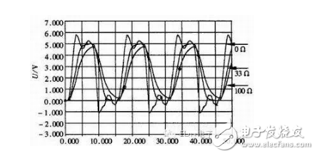
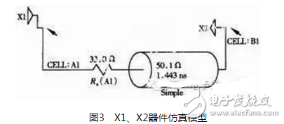
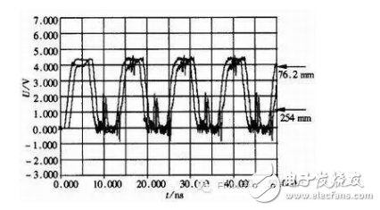
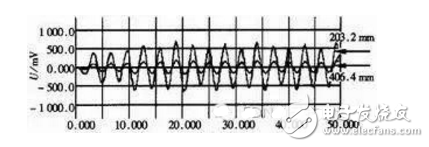
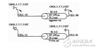
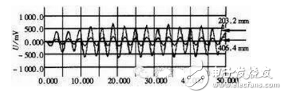
Foreword: The key to the success of high-speed digital system design is to maintain the integrity of the signal, and the factors affecting signal integrity (ie signal quality) are mainly the length of the transmission line, resistance matching, electromagnetic interference, crosstalk and so on. In order to maintain the integrity of the signal during the design process, some simulation tools must be used. The simulation results will give guidance to the PCB layout. After the wiring is completed, the network will be extracted, and the signal will be simulated after wiring. After the simulation has no problem, the processing can be sent out. At present, such simulation tools mainly include cadence, ICX, Hyperlynx, and the like. Hyperlynx is a simple and easy to use tool with two tools, LineSim and BoardSim. LineSim is used to constrain routing and layer parameters before routing design, set clock routing topology, select component speed, diagnose signal integrity, and minimize electromagnetic emissions and crosstalk. BoardSim is used to quickly analyze signal integrity, electromagnetic compatibility, and crosstalk issues in designs, generate crosstalk strength reports, and resolve and resolve crosstalk issues. Using the LineSim tool, the author simulated the signal impedance, the length of the transmission line, and the crosstalk, and gave guiding conclusions. Impedance matching Impedance matching of high-speed digital signals is very critical. If the matching is not good, the signal will generate large overshoot and undershoot. If the amplitude exceeds the threshold of the digital signal, a bit error will occur. There are two types of impedance matching: serial termination and parallel termination. Due to the low power consumption and convenient termination of serial termination, serial termination is generally used in practical work. The effects of termination resistors were analyzed using the Hyperlynx simulation tool below. The simulation IBIS model is built in the 74 series as shown in Figure 1. In the simulation, one receiving end is selected, the transmission line is a strip line, the line width is 0.2 mm, and the dielectric constant is 4.5 (commonly used FR4 material), so that the impedance of the transmission line is 51.7 Ω. Set the square wave with a signal frequency of 50MHz, and the serial termination resistor Rs takes 0Ω, 33Ω and 100Ω respectively for simulation analysis. The simulation results are shown in Figure 2. The signal waveforms at the receiving end when the matching resistance is 0Ω, 33Ω, and 100Ω are indicated in the figure. It can be seen from the waveform that the waveform has a large overshoot and undershoot at 0 Ω, and the signal is the worst; the signal attenuation is large at 100 Ω, the square wave becomes almost a sine wave; and the waveform is better when the matching resistance is 33 Ω. The ideal matching resistance value can be calculated by the software's terminatorWizard tool, which automatically calculates the best matching resistance according to the parameter model of the device to be 33.6Ω, and 33Ω can be used in practical applications. Using the IBIS model of the simulation and the device, the matching resistor value can be known very accurately, so that the signal integrity is controllable. Figure 1 74 series simulation model Figure 2 Simulation results of different serial termination resistors Effect of transmission line length In the design of high-speed digital circuits, in addition to impedance matching, some devices have strict requirements on the length of the transmission line. The higher the signal frequency, the shorter the length of the transmission line is required. Take the X1 device and the X2 device as an example to establish a simulation model as shown in Figure 3. A 33Ω matching resistor was added to the simulation model, and the simulation signal frequency was selected as a 66MHz square wave, and the simulation was performed when the transmission line length was changed to 76.2mm and 254mm, respectively. The simulation results are shown in Figure 4. Figure 4 Simulation results of different length transmission lines It can be seen from the figure that after the signal line is lengthened, the transmission line effect is significantly enhanced due to the increase of the equivalent resistance, inductance and capacitance of the transmission line, and the waveform appears to oscillate. Therefore, in addition to matching resistors in high-frequency PCB layout, the length of the transmission line should be shortened to maintain signal integrity. In the actual PCB layout, if the signal line length cannot be shortened due to the needs of the product structure, differential signal transmission should be used. The differential signal has a strong anti-common-mode interference capability and can greatly extend the transmission distance. There are many kinds of differential signals, such as ECL, PECL, LVDS, etc. Table 1 lists the main features of LVDS relative to ECL and PECL systems. LVDS's constant current source mode low swing output enables LVDS to drive at high speed. For point-to-point connections, the transmission rate can reach 800Mbps. At the same time, LVDS has low noise and low power consumption, and the connection is convenient. The LVDS driver consists of a constant current source, typically 3.5mA, that is used to drive the differential signal lines. The receiver has a high DC input impedance, and all of the drive currents flow through the 10Ω termination resistor, producing approximately 350mV at the receiver input. When the driving state is reversed, the direction of the current flowing through the resistor changes, and an effective logic state is generated at the receiving end. Fig. 5 is a waveform diagram for converting a signal into a differential signal using the LVDS chip DS90LV031 and DS90LV032 for long-distance transmission. In the simulation, the simulation frequency is set to 66MHz ideal square wave, the transmission distance is 508mm, and the differential pair terminal is connected to the differential impedance of the 100Ω load matching transmission line. From the simulation results, the waveform of the LVDS receiving end remains intact except for the delay. Table 1 LVDS, ECL, PECL logic standard comparison table Figure 5 LVDS circuit simulation results Crosstalk analysis Due to the increase of frequency, the crosstalk between transmission lines is obviously increased, which also has a great influence on signal integrity. It can be predicted, simulated and improved by simulation. Take the CMOS signal as an example to establish a simulation model, as shown in Figure 6. In the simulation, the square wave with the interference signal frequency of 66MHz is set, and the interferer is set to the zero level input. The waveform of the receiver end of the victim is observed by adjusting the spacing of the two lines and the length of the parallel line between the two lines. The simulation results are shown in Fig. 7, which are waveforms with a pitch of 203.2 mm and 406.4 mm, respectively. Figure 6 Crosstalk model Figure 7 Crosstalk simulation results at different pitches From the simulation results, the crosstalk level is about 200mV when the two-wire spacing is 406.4mm, and about 500mV at 203.2mm. It can be seen that the smaller the spacing between the two lines is, the larger the crosstalk is. Therefore, in the actual high-speed PCB layout, the transmission line spacing should be increased as much as possible or the ground line should be added between the two lines to isolate. In high-speed digital circuit design, it is difficult to predict and guarantee signal integrity without using simulation and traditional design methods or experience. Simulation has become a necessary means for high-speed signal design. Simulation can predict signal transmission and improve system performance. reliability. KNL5-63 Residual Current Circuit Breaker
KNL5-63 Moulded Case Circuit Breaker is MCCB , How to select good Molded Case Circuit Breaker suppliers? Korlen electric is your first choice. All moulded Case Circuit Breakers pass the CE.CB.SEMKO.SIRIM etc. Certificates.
Moulded Case Circuit Breaker /MCCB can be used to distribute electric power and protect power equipment against overload and short-current, and can change the circuit and start motor infrequently. The application of Moulded Case Circuit Breaker /MCCB is industrial. KNL5-63 Molded Case Circuit Breaker,Small Size Molded Case Circuit Breaker,Electrical Molded Case Circuit Breaker,Automatic Molded Case Circuit Breaker Wenzhou Korlen Electric Appliances Co., Ltd. , https://www.zjmannualmotorstarter.com![]() The key to the success of high-speed digital system design is to maintain the integrity of the signal, and the factors affecting signal integrity (ie signal quality) are mainly the length of the transmission line, resistance matching and electromagnetic interference, crosstalk and so on.
The key to the success of high-speed digital system design is to maintain the integrity of the signal, and the factors affecting signal integrity (ie signal quality) are mainly the length of the transmission line, resistance matching and electromagnetic interference, crosstalk and so on. 

Korlen electric also provide Miniature Circuit Breaker /MCB. Residual Current Circuit Breaker /RCCB. RCBO. Led light and so on .