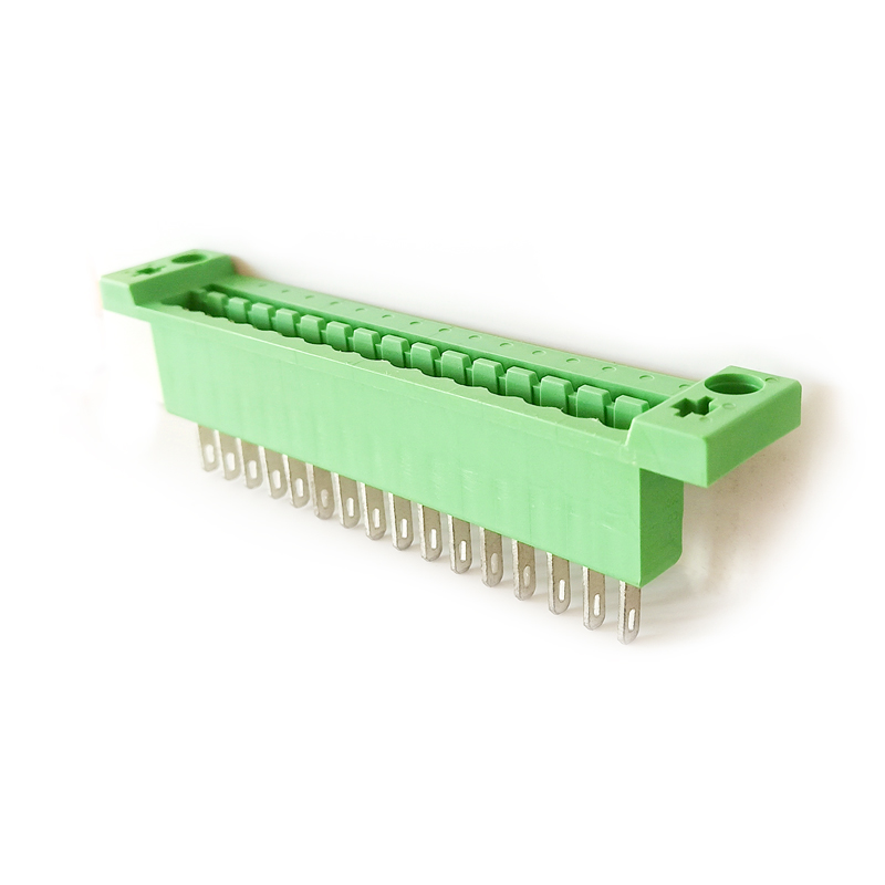
The composite terminal is a typical representative of the connector (CONNECTOR), which is composed of a plug (female) and a socket (male) to realize the connection function. For the transfer of voltage, current and signal, this series is characterized by safe, reliable and stable contact, and is mainly used in electric power, communication, industrial control and other industries.
composite terminal block,component terminal block,composite terminal block adapter Sichuan Xinlian electronic science and technology Company , https://www.sztmlch.com Fiber-based multi-channel LED test system
principle
The LED optical signal is collected through the optical fiber , and is converted into a LED test ( analysis ) module through photoelectric signal conversion. The analysis data is imported into the computer through various data interfaces, and is connected to the ICT online test and the function test program to generate a data report. 
2, using a color sensor for photoelectric conversion. It not only reduces equipment costs, but also enables high-speed multi-channel acquisition of signals. The traditional integrating sphere cannot measure multiple LEDs at the same time, and only one integrating sphere can be connected to one PC, which makes the production efficiency extremely low. The use of single-chip microcomputer with color sensor, can expand the IO port through the outside to achieve multi-channel high-speed acquisition of optical signals, the number of LED test can reach more than 600 at a time, so that LED test out of the laboratory, in the actual production of the factory.
3. The application of various mathematical function models makes the measurement of optical parameters such as wavelength and color temperature more accurate. Since the color sensor can only collect RGB values ​​and cannot obtain the spectrum of the LED, a variety of mathematical models are established in the program to establish a color coordinate system by performing complex mathematical processing on the continuously acquired RGB values, and then in color. The wavelength and color temperature of the LED are calculated in the coordinates. Accuracy is up to 1NM. A set of equipment can simultaneously measure wavelength, color temperature, color coordinates and other parameters. Greatly reduce equipment costs and improve equipment capabilities. 


Fiber-based LED tester software system - real-time test demonstration
Introduction
The input part uses optical fibers and a light collecting head to collect optical signals, and the color sensor converts the optical signals into electrical signals. The acquired electrical signal is digital-to-analog converted by the single-chip microcomputer, and the data is transmitted to the PC through the USB. The PC analyzes and processes the data, the analysis time does not exceed 500mS, and the display interface is written by VB. It can measure the main optical parameters such as color, brightness, wavelength, color coordinate and color temperature of LED, with high precision and fast speed. Multiple LED lights can be measured simultaneously.
Technical characteristics
1, using optical fiber and lighting head to collect optical signals. It effectively avoids the diffraction interference between adjacent LED lamps, and also gives a more relaxed requirement for the test environment, so as to conduct LED test in the ordinary workshop instead of the black box.
 
 
Program interface
Actual operation
Â
This program is a fully automatic test system, the steps are as follows:
1. Put the product into the fixture and press the fiber
2. Click the test program "TEST" button to start the test. Ready indicates preparation. OPENING PORT indicates that the test port is being opened. CAPTURING indicates that data is being fetched. READING FIBER N indicates that data for one fiber is being read. TEST FINISHED indicates that the test is complete.
3, the test is completed. The test results are automatically saved in EXCEL format. The test interface shows PASS or FAIL.