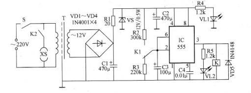
The schematic diagram of the food mixer timing protector circuit is shown in the figure. The circuit is mainly composed of two parts: 555 time base integrated circuit and power supply circuit.
After closing S to turn on the power, 220V AC is stepped down by transformer T, VD1 - VD4 bridge rectifier, VS regulated output is about 12V DC for 555 time base integrated circuit power. The 555 time base integrated circuit and R2, R3, C3, etc. form a gap timing controller, R2 is a delayed release charging resistor, R3 is a delay pull-in discharge resistor, and C3 is a timing capacitor. At the moment of closing S, because the voltage across C3 is zero, the 555 time base integrated circuit is set, the 3 pin output is high level, the relay K is energized, and the contact K2 is closed to turn on the mixer power supply (the mixer's power plug is inserted in this The machine socket XS) makes it work. At the same time, the other switching contact K1 is turned to the normally open end, that is, to the R3 terminal. At this time, the power supply charges the capacitor C3 through R2, so that the potential of the 6-pin integrated circuit of the 555 time-base integrated circuit rises continuously, and the potential of the 6-pin rises after about 20 seconds. 2/3 of the power supply voltage, 555 time base integrated circuit reset, 3 pin output low level, relay K loses power release, contact K2 opens, socket XS stops supplying power to the mixer. At the same time, K1 is turned to the normally closed end, that is, it is reversed to the R3 end. At this time, the stored charge of C3 is discharged through R3, so that the potential of the 2 pin of the 555 time base integrated circuit is continuously decreased. After about 15 seconds, the level is lowered to 1/ of the power supply voltage. 3,555 time base integrated circuit is set, 3 feet output high level, K is energized and pulled, the mixer has electricity work, so repeatedly, the mixer can work automatically for 20s, rest for 15s, thus ensuring that the mixer motor will not overheat damage.
The start-up and stop-time of the protector are determined by the resistors R2 and R3 respectively. Adjusting the resistance values ​​of the two resistors can determine the start-up and stop-time respectively, which can be adjusted according to the actual situation, or the two resistors can be changed to the potential. To make it easy to adjust startup and downtime at any time.
The VU is the protector power indicator that illuminates as long as the protector is powered. VL2 is the working indicator of the mixer. When K2 is closed and the mixer is energized, it lights up. If V1.2 is off, it means that the socket XS stops sending power, and the mixer does not work.
wrist watch accessories,watch parts,custom watch accessories,watch parts customize
Dongguan Yingxin Technology Co., Ltd. , https://www.yingxinwatch.com