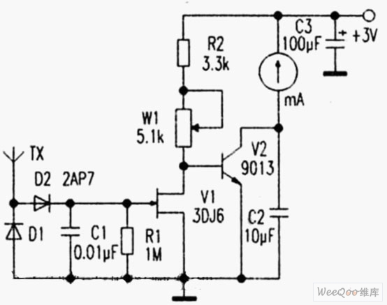
High sensitivity field strength circuit The figure shows the high-sensitivity field strength meter circuit. The circuit composed of the antenna TX, the diodes D1, D2, and the capacitor C1 receives a high-frequency signal, and generates a DC voltage after being detected. After V1, V2 amplification. Push the ammeter indication, adjust the base voltage of W1 to control V2, and then change the indication of the ammeter to achieve the effect of adjusting the sensitivity. During production, D1 and D2 select detector diode 2AP7 (cutoff frequency >150MHz), and V1 selects junction field effect transistor such as 3DJ6, 3DJ8 and so on. V2 can be 9013 or 9014 (β>140), and the antenna uses a small rod antenna. After the production is completed, the circuit should be placed in the shield to avoid external electric field interference. When using, connect the power supply and multimeter, turn the multimeter to 5mA, adjust W1 to make the hands full, because the stronger the antenna sensing signal, the smaller the deflection of the hands. Use this field strength meter to measure the local oscillator of the radio, and the hands have obvious swing. Electrical Meter Sockets,LCD Power Meter Socket,Digital Power Meter Socket,Power Meter Plug Socket NINGBO COWELL ELECTRONICS & TECHNOLOGY CO., LTD , https://www.cowellsockets.com