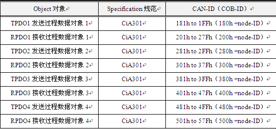
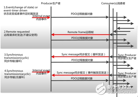
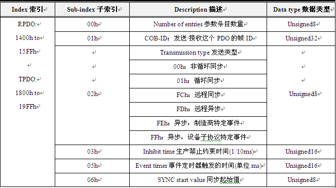
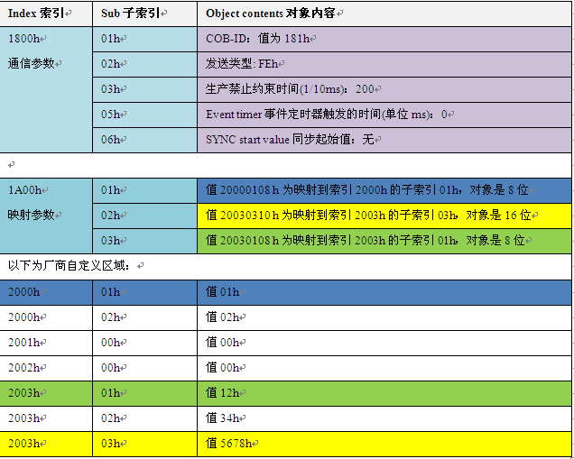
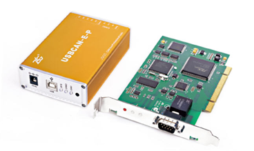
Process data object (PDO) PDO belongs to the process data used to transmit real-time data, that is, one-way transmission, without the receiving node responding to the CAN message to confirm, in terms of communication terminology, it belongs to the “production consumption†model PDO, as shown in Figure 1, just like the food sales counter. Producers put out "food", but only consumers who "need" will buy it, without directivity. Figure 1 Producer Consumer Model The data length is limited to 1~8 bytes. A message or a variable can be passed at most one frame at a time. PDO CAN-ID definition PDO communication is flexible. In general, as long as all CANIDs in the PDO range can be used as the node's own TPDO or RPDO, also known as COB-ID, it is not limited by the function code and Node-ID, as shown in Figure 2. Figure 2 PDO CANID rules In the PDO pre-defined, the TPDO and RPDO are specified artificially, the location of the Node-ID in the PDO is specified, and the number of the PDO is specified, as shown in Table 1. Table 1 CAN-ID definition of PDO The PDO is divided into TPDO (transmit PDO) and (receive RPDO), and the transmission and reception are referenced by the CANopen node itself (if the CAN master or other slaves are the opposite). TPDO and RPDO have 4 data objects respectively, each data object is a CAN message encapsulation, these are the containers for data transceiving. As shown in Figure 3, the fruit basket is ready for the user, it depends on the user. What fruit is inside? Figure 3 PDO and SDO are like fruit baskets Of course, if a node needs to pass a lot of resources, there are data objects such as TPDO5, and their CAN-ID definition needs to break the predefined rules. For example, we can define a node with Node-ID 1. The middle TPDO5 is 182h, and the lower 7 bits of the COB-ID of the PDO here are no longer the Node-ID. In fact, all the PDO's COB-ID and Node-ID have no necessary rules. PDO transmission form Two transmission modes of PDO: synchronous transmission and asynchronous transmission. As shown in FIG. 4, 1, 2 are asynchronous transmissions, and 3 and 4 are synchronous transmissions. Figure 4 PDO transmission form Asynchronous transfer (triggered by a specific event) There are two ways to trigger. The first one is triggered by an object-specific event specified in the device sub-protocol (for example, timing transmission, data change transmission, etc.). The second is to trigger the transmission of PDO by sending the same remote frame as the COB-ID of the PDO. The asynchronous transmission in the current application basically adopts the first one. Synchronous transmission (synchronization by receiving synchronization objects) Synchronous transmission is to enable all nodes to upload data or execute application instructions at the same time by synchronizing messages, which can effectively avoid the problem of application logic confusion and bus load imbalance caused by asynchronous transmission. Generally, the node that sends the synchronization message is the NMT host. Synchronous transmission can be divided into periodic transmission (cyclic) and acyclic transmission (no loop). The periodic transmission is realized by receiving the synchronization object (SYNC), and can set 1~240 synchronization object triggers. Aperiodic transmissions are pre-triggered by remote frames or pre-triggered by object-specific events specified in the device sub-protocol. PDO communication parameters The PDO communication parameter defines the COB-ID, transmission type, timing period, etc. used by the device. The RPDO communication parameters are located at 1400h to 15FFh of the object dictionary index, and the TPDO communication parameters are located at 1800h to 19FFh of the object dictionary index. Each index represents a communication parameter set of a PDO, wherein the sub-indexes respectively point to specific various parameters. As shown in table 2. Table 2 PDO communication parameters Number of entries parameter entries: there are several parameters in this index; ?COB-ID: the corresponding CAN frame ID sent or received by this PDO; Type of transmission: the form of transmission that this PDO sends or receives, usually using cyclic synchronization and asynchronous manufacturer-specific events; ?Inhibit TIme production prohibition constraint time (1/10ms): Constrain the minimum interval of PDO transmission, avoiding the bus load drama If the digital input is too fast, the TPDO sent by the status change is frequently sent, and the bus load is increased, so a constraint time is needed to perform "filtering", the time unit is 0.1 ms; • Event TImer event timer trigger time (in ms): The time the PDO is sent, its timing time. If this time is 0, then this PDO is sent for event change. SYNC start value Synchronization start value: The PDO of the synchronous transmission is sent only after receiving the synchronization packets of Nogan. The synchronization start value is the number of synchronization packets. For example, if it is set to 2, it will be sent after receiving 2 synchronization packets. PDO mapping parameters The PDO mapping parameter is a difficult point for beginners to learn CANopen. It contains a list of objects in the object dictionary. These objects are mapped to the corresponding PDO, including the length (unit, bit) of the data, for both producers and consumers. It is necessary to know this mapping parameter in order to correctly interpret the PDO content. It is to link the communication parameters, application data and data in specific CAN messages. RPDO communication parameter 1400h to 15FFh, mapping parameter 1600h to 17FFh, data storage is 2000h after vendor custom area; TPDO communication parameter 1800h to 19FFh, mapping parameter 1A00h to 1BFFh, data storage is 2000h after vendor custom area. In order to express the mapping more intuitively, Table 3 simulates TPDO1, and combines parameters, application data, and CAN message data to display different mappings in different colors. Table 3 PDO mapping in the object dictionary CAN transmission (CAN send message) TPDO1 (CAN-ID = 181h) Data field: 4 bytes of data field Table 4 TPDO data fields Read the reader more than 3 times, if you still can't understand. Please open the CANopen master card management software CANManager for CANopen from Guangzhou Zhiyuan Electronics, and import the EDS file of the XGate-COP10 module slave protocol stack module to get a real experience. Click on Configure Substation to make a perceptual understanding in "Advanced". The USBCAN-EP and PCI-5010-P master card can expand the CANOpen communication interface for the PC and realize the data communication of the CANOpen protocol. As the administrator of the CANOpen network, it implements all CANOpen Network Management (NMT) functions.
60CM Range Hoods
Range Hoods Downdraft Cooker Hood,Range Hoods,Kitchen Hood,Ceiling Built In Hood xunda science&technology group co.ltd , https://www.gasstove.be



Stainless steel + tempered glass
Suction power: 760m³/h air flow
3 speed electronic switch
1x6 layers washable aluminum grease filters
2x2W LED lamps
Rated input power (motor): 170W
