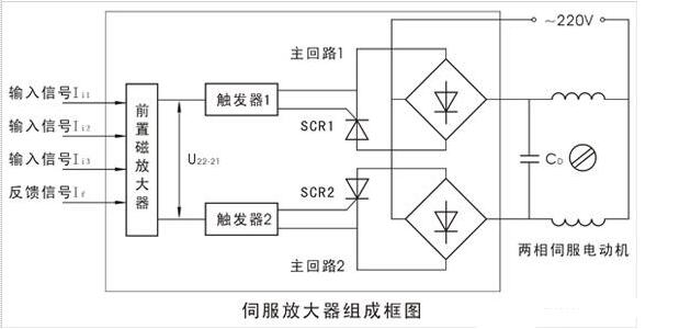
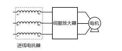
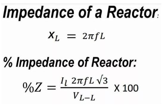
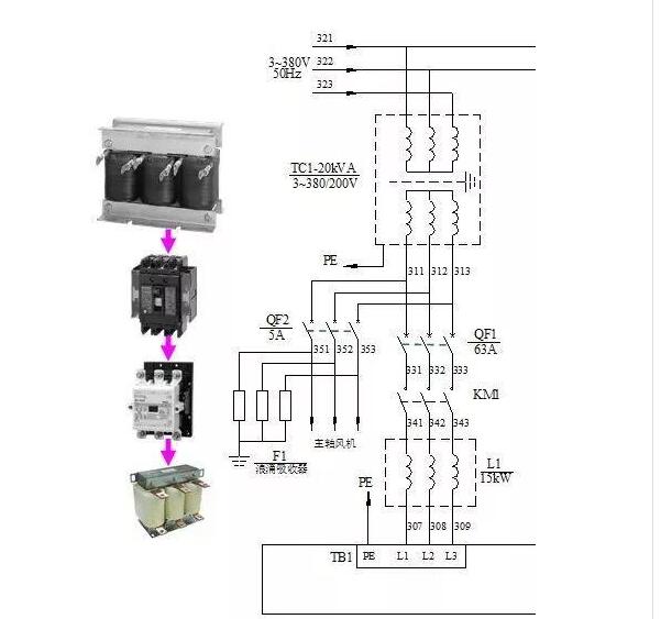
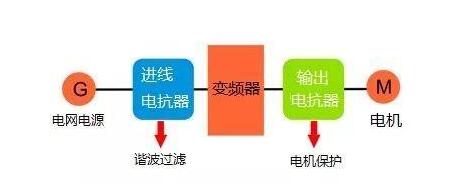
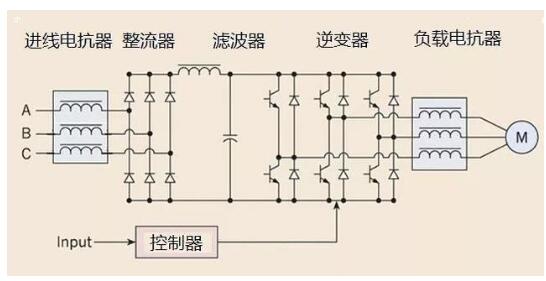
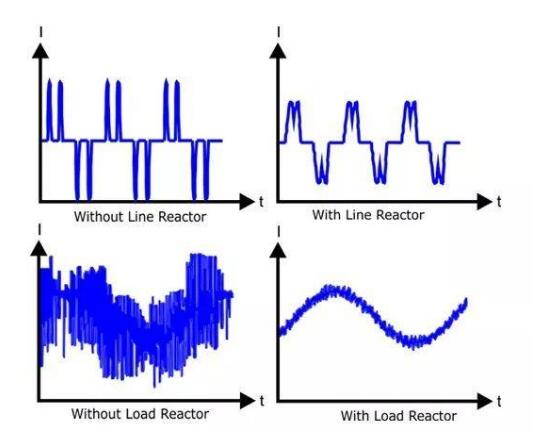
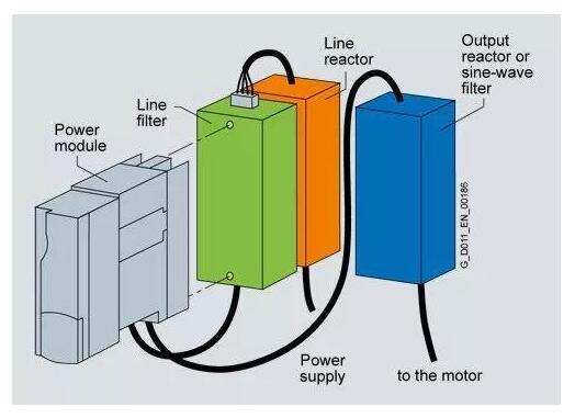
This article mainly explains the reasons for using the reactor before the servo amplifier. First, it introduces the function and principle of the servo amplifier. Secondly, it explains why the reactor should be solved before the servo amplifier. Follow the small series to learn more about it. The function of the servo amplifier is to synthesize and amplify a plurality of input signals and feedback signals, and output corresponding signals according to the polarity of the integrated signals to control the servo motor to rotate forward or reverse. When the input signal and the feedback signal are balanced, the servo motor stops rotating and the output shaft of the actuator is stabilized at a certain position. The servo amplifier group is composed of a pre-magnetic amplifier, a flip-flop, a thyristor main circuit, and a power supply, and its composition is as shown in the following figure. To accommodate the need for complex multi-parameter adjustments, the servo amplifier is configured with three input signal channels and one position feedback signal path. Therefore, it can input three input signals and one position feedback signal at the same time. In a single-parameter simple adjustment system, only one of the input and feedback channels is used. In the servo amplifier, the pre-amplifier combines the three input signals and one feedback signal into a deviation signal and amplifies it into a voltage signal U22-21 output. The output voltage is simultaneously converted into a trigger pulse by the trigger 1 (or 2) to control the thyristor conduction of the thyristor main circuit 1 (or 2), thereby applying an AC 220V power supply to the two-phase servo motor winding to drive the two-phase servo motor. Turn. When △1》0, U22-21′0, trigger 2 and main circuit 2 work, two-phase servo motor rotates forward; when △1 “0, trigger 1 and main circuit 1 work, two-phase servo motor Inverted; the circuit composition and parameters of the two sets of flip-flops and the two sets of thyristor main loops are identical, so when the input signal is balanced with the position feedback current If, the output of the pre-magnetic amplifier is U22-21≈0, both flip-flops There is no trigger pulse output, the thyristors in the main circuits 1 and 2 are blocked, the power of the two-phase servo motor is turned off, and the motor stops rotating. It can be seen that the servo amplifier is equivalent to a three-position non-contact relay and has a large power amplification capability. The servo amplifier is an important part of the motion control system. It provides a power supply with adjustable servo motor frequency to achieve high-precision transmission system positioning. It is currently a high-end product of transmission technology. The use of servo amplifiers ranging from a few thousand to more than 10,000 yuan should be very careful to maximize their service life. The sudden change of the grid voltage and the current surge caused by the operation of the overvoltage, harmonic interference, spikes contained in the voltage, etc., are very damaging to the sensitive components in the servo amplifier loop. A reactor (called a line reactor) is installed in front of the servo amplifier to protect the drive from the above impact, as shown in Figure 1. Figure 1 Line reactor 1. Reactor and its function A reactor, as the name suggests, is a device that acts as an impedance in a circuit. The wire is wound into a solenoid form, and the iron core is inserted into the solenoid, so that the inductance is large, and it becomes a reactor, which is actually an inductor. The ratio of the voltage drop across the reactor to the line voltage, called the reactance rate, characterizes the reactor parameters. The impedance and reactance of the reactor are shown in Figure 2. The typical reactance is 3% or 5%. Figure 2 Impedance calculation and reactance formula It can be seen that the greater the current frequency of the reactor, the greater the impedance, which is the principle that the reactor can smooth the peak voltage and suppress the harmonics (see the blue word to see the harmonics). Moreover, learning harmonics, you know that servo amplifiers, frequency converters are important harmonic sources, is the culprit of grid pollution. After the reactor is installed, it can prevent interference from the power grid, protect the servo amplifier, and reduce the pollution of the grid generated by the harmonic current generated by the rectifier unit of the servo amplifier. 2, reactor symbol The symbols in the electrical diagram of the reactor are the same as the inductance, and are indicated by L. Figure 3 shows the main power input circuit diagram of the FANUC βi SVSP servo amplifier. L1 is the line reactor. Figure 3 A servo amplifier main power input circuit diagram 3, output reactor The reactor is installed between the inverter and the motor, called a load reactor or an output reactor to protect the motor, as shown in Figure 4. Figure 4 output reactor The detailed principle is shown in Figure 5. Figure 5 Schematic diagram of the connection between reactor and drive system How much effect does a reactor and a reactor have on smooth current? As shown in Figure 6, the reactor can smooth the transient voltage and suppress harmonics. Figure 6 Comparison of the effect of the reactor with or without reactor 4, the power filter Electromagne interference (EMI) is also a major problem in servo drive systems, so the line reactor is equipped with a line filter at the input of the power module to suppress electromagnetic interference. Figure 7 shows. Figure 7 Power Filter Use The FANUC servo amplifier manual often mentions AC reactor and AC line filter. Do you understand the role of these things now? Why install a reactor in front of the servo amplifier in order to suppress harmonic interference from the power supply grid, smooth the spikes contained in the power supply voltage, improve the power quality of the servo amplifier, and protect sensitive components in the loop. Piezoelectric Buzzer For External Drive The piezoelectric transducers (for External
Drive) produce exceptional sound output and efficiency all while meeting each
customers unique performance requirements. Piezo transducers are constructed
without magnets, instead they create sound mechanically via the piezoelectric effect.
Our piezo transducers are not equipped with a built in drive circuit. This
provides our customers with the flexibility of designing their own circuitry to
meet their specific needs. The advantage of using an external drive circuit is
that the piezo transducers can output sounds at multiple frequencies. Full
bridge circuits ramp up SPL for more peak-to-peak voltage, making our piezo
transducers a high output solution.
Piezo Alarm Buzzer,Alarm Piezo Buzzer,Fire Alarm Piezo Buzzer,Active Magnetic Buzzer Jiangsu Huawha Electronices Co.,Ltd , https://www.hnbuzzer.com