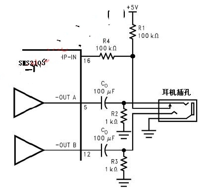
Figure 1 is a schematic diagram of the operation of the headphone control function. When no headphone plug is connected to the jack, the R1-R2 voltage dividing resistor makes the voltage supplied to the HP-IN pin (16 pin) approximately 50mV, and drives Amp1B and Amp2B to work. To make the HWD2163 work in bridge mode. The output coupling capacitor isolates the half supply DC voltage to protect the headphones. This article refers to the address: http:// The voltage at the input HP-IN pin is 4V. When the HWD2163 is operating in bridge mode, the voltage across the load is essentially 0V. Therefore, even in an ideal state, it is difficult to cause the amplifier to operate in a single-terminal output mode. Connecting the headphone jack to the headphone jack separates the headphone jack from -OUTA and connects R1 to the HP pin to VDD. In this way, the headphone off function turns off the Amp2A and Amp2B and the bridge-connected speakers do not work. The amplifier drives the headphone with the output coupling impedance of R2 and R3. When the headphone impedance is 32Ω, the output coupling impedance is R2. The effect of R3 on the output drive capability of the HWD2163 is negligible. Figure 2 is also a schematic diagram of the electrical connection relationship of the headphone jack. The jack is a set of three-wire plug design. The tip and the ring are respectively a signal output of the stereo two-channel, but the outermost ring is ground. When the headphones are connected, a headphone jack with a console connection is sufficient to drive the HP-IN pin. A microprocessor or switch can replace the function of the control terminal in the headphone jack. The microprocessor or switch provides 4V~VDD voltage to the HP-IN, so the bridge mode connecting the speakers stops working and the Amp1A and Amp2A drive the headphones respectively. Left and right channels. 401-999Kva Diesel Generator,Shanghai Genset,Shanghai Power Generator,Power Generator Set Shanghai Kosta Electric Co., Ltd. , https://www.shkostagenerator.com