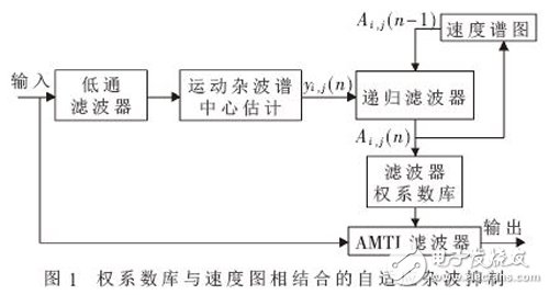
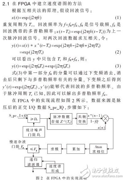
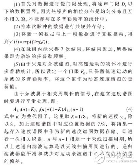
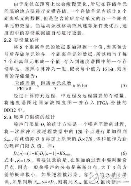
Abstract: In radar signal processing, in order to effectively suppress low-speed motion clutter, a method for establishing clutter velocity spectrum is studied. The establishment of this clutter velocity spectrum is realized in the FPGA, and the motion clutter velocity map is obtained by processing the radar actual echo data in the FPGA. The experimental results show that the clutter velocity spectrum designed by this method is consistent with the simulation results, which can effectively suppress the clutter of static and slow motion. And because of the high-efficiency processing capability of the ultra-large-scale programmable device, the engineering is convenient and flexible, and has strong practicability. The effective suppression of clutter and interference has become a major research direction of radar signal processing. The clutter environment faced by modern radar is quite complicated. The common moving target cancellation system mainly has a good suppression effect on fixed ground clutter, but it has a certain speed of motion such as meteorology, waves and chaff. In the case of waves, the center of the clutter spectrum deviates from the zero Doppler frequency. If no effective measures are taken, such clutter will not be well removed [1-2]. Therefore, considering the motion of the clutter and the regional time-dependent degeneration, it is a good choice to establish a dynamic clutter velocity spectrum in order to adaptively suppress the low-speed motion clutter. Existing literatures have studied more on clutter contour maps and clutter amplitude maps [3-6]. The clutter contour map can be used to select the normal branch and the MTD (or MTI) coherent processing branch. The data in the clutter contour map is processed after the coherent signal processing, and the portion outside the clutter contour map is taken normally. Branch output, thereby improving the detection ability of weak targets in weak clutter or no clutter conditions [6]. The clutter amplitude map can be used in constant false alarm detection. References [7] and references [8] have studied the formation and application of three-dimensional clutter maps. At present, there are relatively few studies on the clutter velocity map. For the motion clutter, after the Doppler frequency is calculated, there are generally two methods to suppress the clutter [9]: (1) The motion clutter spectrum center compensation is performed on the echo signal u(t), and the motion clutter spectrum is obtained. The center moves to zero frequency, and then uses the MTI filter with the notch at zero frequency to suppress the motion clutter; (2) directly uses the MTI filter with the notch at fd to suppress the motion clutter, and the MTI of the notch at fd The filter weight coefficients can be pre-stored in a library of filter weight coefficients, as shown in Figure 1. Whether it is Doppler center compensation for motion clutter or the weight library method, it is necessary to calculate the center of the motion clutter spectrum, that is, the speed of motion clutter. Therefore, a method for finding the clutter velocity spectrum is designed here. The speed of the slow moving clutter is calculated, and the Doppler center frequency of the clutter is stored. Using the efficient processing capability of the FPGA, the clutter is realized by software programming. The establishment of the velocity spectrum makes the project easy to implement. 2 Speed ​​spectrum implementation There are many ways to find the clutter speed. One is the classical spectral estimation FFT method. The speed precision is related to the number of points of the FFT. In the case where the signal re-frequency is known, the higher the FFT point, the higher the speed resolution accuracy. It is also possible to use arctan to find the phase difference to find the clutter speed. In the operation of solving the inverse tangent function, the traditional methods include table lookup method, polynomial approximation method, table lookup and polynomial combination method, bitwise method, etc. [10]. However, these methods fail to meet speed and accuracy requirements and hardware implementation difficulties. In order to facilitate the implementation in the FPGA, suitable for the operation flow in the FPGA, the design selects the cross-correlation method to solve the Doppler velocity. USB4 specifies tunneling of:
40 Gbps Maximum Speed: By using two-lane cables, devices are able to operate at up to 40 Gbps, the same speed as Thunderbolt 3. The data is transmitted in two sets of four bidirectional lanes.
DisplayPort Alt Mode 2.0: USB 4 supports DisplayPort 2.0 over its alternative mode. DisplayPort 2.0 can support 8K resolution at 60 Hz with HDR10 color. DisplayPort 2.0 can use up to 80 Gbps, which is double the amount available to USB data, because it sends all the data in one direction (to the monitor) and can thus use all eight data lanes at once.
Better Resource Allocation for Video, PCIe: In lieu of alternative mode where the other interface takes over the connection, USB 4 devices can use a process called "protocol tunneling" that sends DisplayPort, PCIe and USB packets at the same time while allocating bandwidth accordingly.
Usb4 Cable,Usb To Usb4,Usb 4 Cable,Usb 4 Wires UCOAX , https://www.ucoax.com


USB 3.2 ("Enhanced Superspeed") Tunneling
DisplayPort 1.4a -based Tunneling
PCI Express (PCIe)-based Tunneling
Main Benefits of USB 4
The new USB 4 standard has three main benefits over prior versions of USB.