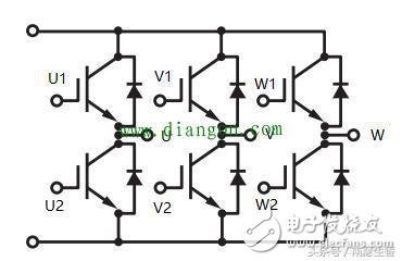
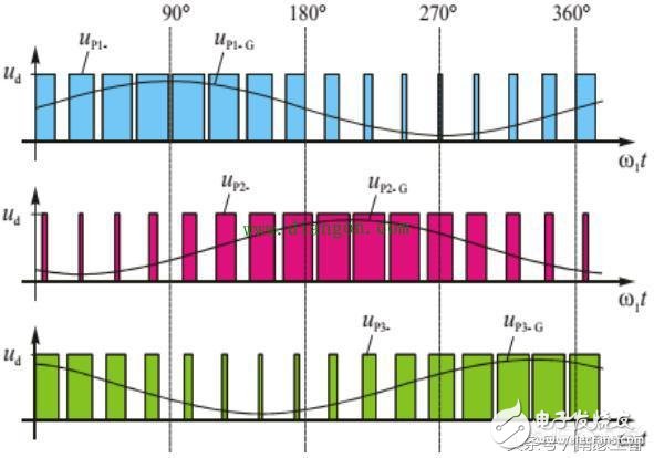
In the inverter control, the three-phase inverter bridge is currently used, as in the following figure. U1, U2, V1, V2, W1, W2 in the three-phase inverter bridge are driving signals for controlling six IGBTs; The three-phase inverter bridges U, V, W are respectively connected to the terminals of the three-phase windings of the motor; the working principle of the three-phase inverter bridge is briefly introduced here, the upper end of the inverter bridge is connected to the positive end of the DC voltage, and the lower end Connected to the negative terminal of the DC voltage, where the DC voltage is VDC. The three-phase bridge is composed of three bridge arms. In the above figure, U1, U2 controlled IGBTs form a bridge arm; V1, V2 controlled IGBTs form a second bridge arm; W1, VW2 controlled IGBTs constitute a third bridge arm; Therefore, when U1 is high level and U2 is low level, the IGBT of the upper arm is turned on, and the IGBT of the lower arm is turned off, so that the voltage of the negative terminal of the U relative to the inverter bridge of the motor is about the DC voltage of the inverter bridge. The value is VDC. Conversely, when U1 is low and U2 is at an electrical level, the IGBT of the upper arm is turned off, and the IGBT of the lower arm is turned on, so that the voltage of the U of the motor relative to the negative terminal of the inverter bridge is about 0V. The other two phases have the same function. Therefore, when the three-phase inverter bridge is working, if an oscilloscope is used to measure the voltage between the U and the negative terminal of the DC power supply, the voltage waveform seen is a PWM waveform whose duty cycle has been changing, and the PWM wave is high. The flat voltage value is about VDC, as shown in the following figure, Up1-, Up2-, Up2-, and the PWM wave is the carrier of the title, and its frequency is the carrier frequency. Since the duty cycle of the carrier is constantly changing, its average voltage or equivalent voltage also varies in one cycle. The smaller the duty cycle, the smaller the equivalent voltage, and the larger the duty cycle, the larger the equivalent voltage. This equivalent voltage is Up1-G, Up2-G, Up3-G in the figure below. This waveform is the fundamental wave, and the fundamental frequency is the fundamental frequency. If you test the voltage waveform with an oscilloscope, you can get the fundamental waveform by changing the bandwidth of the probe to a suitable value. Regular GFCI Receptacle Outlet Lishui Trimone Electrical Technology Co., Ltd , https://www.3gracegfci.com
