I-Beam Inductors,Chip Inductors,Color Ring Inductor,R-Bar Inductors Shenzhen Sichuangge Magneto-electric Co. , Ltd , https://www.scginductor.com
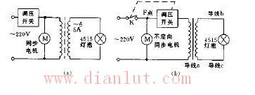
Figure a is the wiring diagram of the original scanning lamp. The effect of this use will make the dancer sometimes feel very glaring, very uncomfortable, and sometimes make the scanning light still, is to scan effect. This is because the dimmer switch not only adjusts the light, but also adjusts the speed of the synchronous motor. When the brightness of the scanning lamp is adjusted to the appropriate level, the operating voltage of the motor is adjusted to below 180V to stop the motor.
If the voltage regulating switch is connected to the circuit shown in Figure b, the live wire of the scanning lamp rotating motor is taken out from the light box and connected to the voltage point of the voltage regulating switch, so that the motor is not controlled by the voltage regulating switch, and the brightness of the scanning light can be Adjust it arbitrarily.
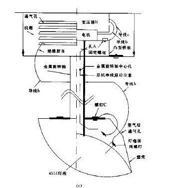
Figure c is an outline view of the scanning lamp. The original lamp lead wire is inserted through the center hole of the metal rotating shaft, and is passed through the hole A. Since the rotating shaft such as scanning is continuously rotated by 180° or 360°, use It has been found that the twisting of the wire in the center hole of the rotating shaft is a frequent failure. The lighter will cause the light to be dark when it is light. If the light is not short-circuited or disconnected from the outer surface, the transformer will be burnt.
This allows the secondary output lead b of the transformer to pass through the vent hole of the chassis. When the vent hole is vented, the tape is reinforced and then penetrated from the rear hole of the plastic case of the bulb and fixed to the pole of the bulb through the terminal. The secondary output lead c of the transformer is first fixed with the screw on the convex iron plate of the fixed motor, and the lamp housing is used as a length of wire. At the screw, the other electrode of the 4515 bulb is connected with a wire (4~5cm). Ok. 
